Window blind structure

Inactive Publication Date: 2007-04-19
NIEN LESLIE
View PDF6 Cites 38 Cited by
  • Summary
  • Abstract
  • Description
  • Claims
  • Application Information

AI Technical Summary

Benefits of technology

[0004] It is, therefore, the primary purpose of the present invention to provide a window blind structure, comprising a blind body and a set of left and right support brackets wherein around four side corners of each extension portion of the left/right support brackets are respectively disposed a thru-hole accompanied by a set of first and second positioning blocks to match with an adjusting support member that, depending on the position of the left/right support brackets fixed to a vertical/horizontal wall surface, can flexibly change the direction of assembly for the mounting of a hanging rod thereon accordingly, achieving more versatile and convenient ass

Problems solved by technology

However, there are some drawbacks to such conventional blind structure.
First, the fixing surface 153 of the support bracket 15, except being mounted to a vertical wall surface, cannot be flexibly assembled other kind of wall surface like a horizontal one, which makes it rather limited and inconvenient in terms of app

Method used


Image

  • Window blind structure
  • Window blind structure
  • Window blind structure

Examples


Embodiment Construction

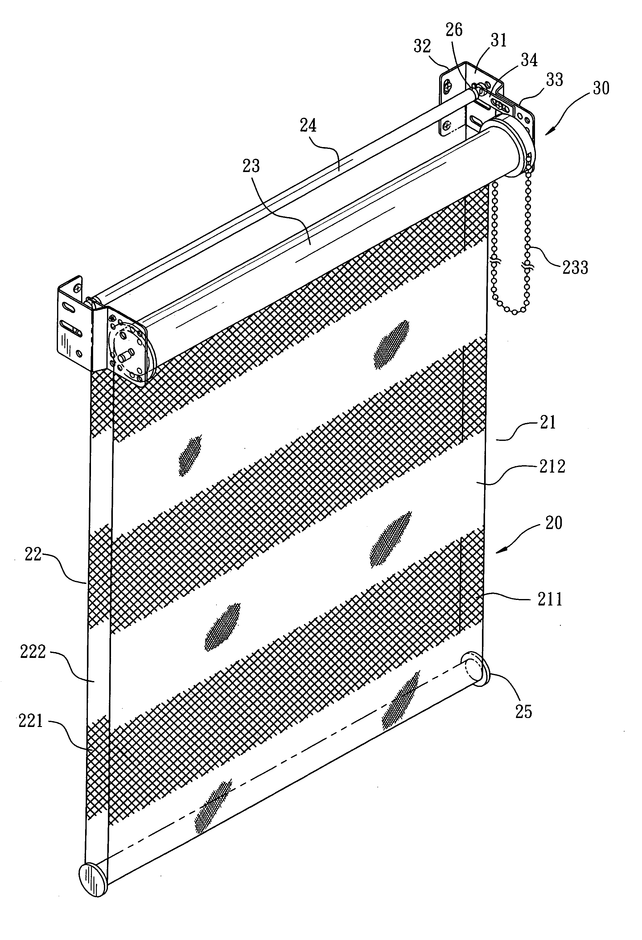
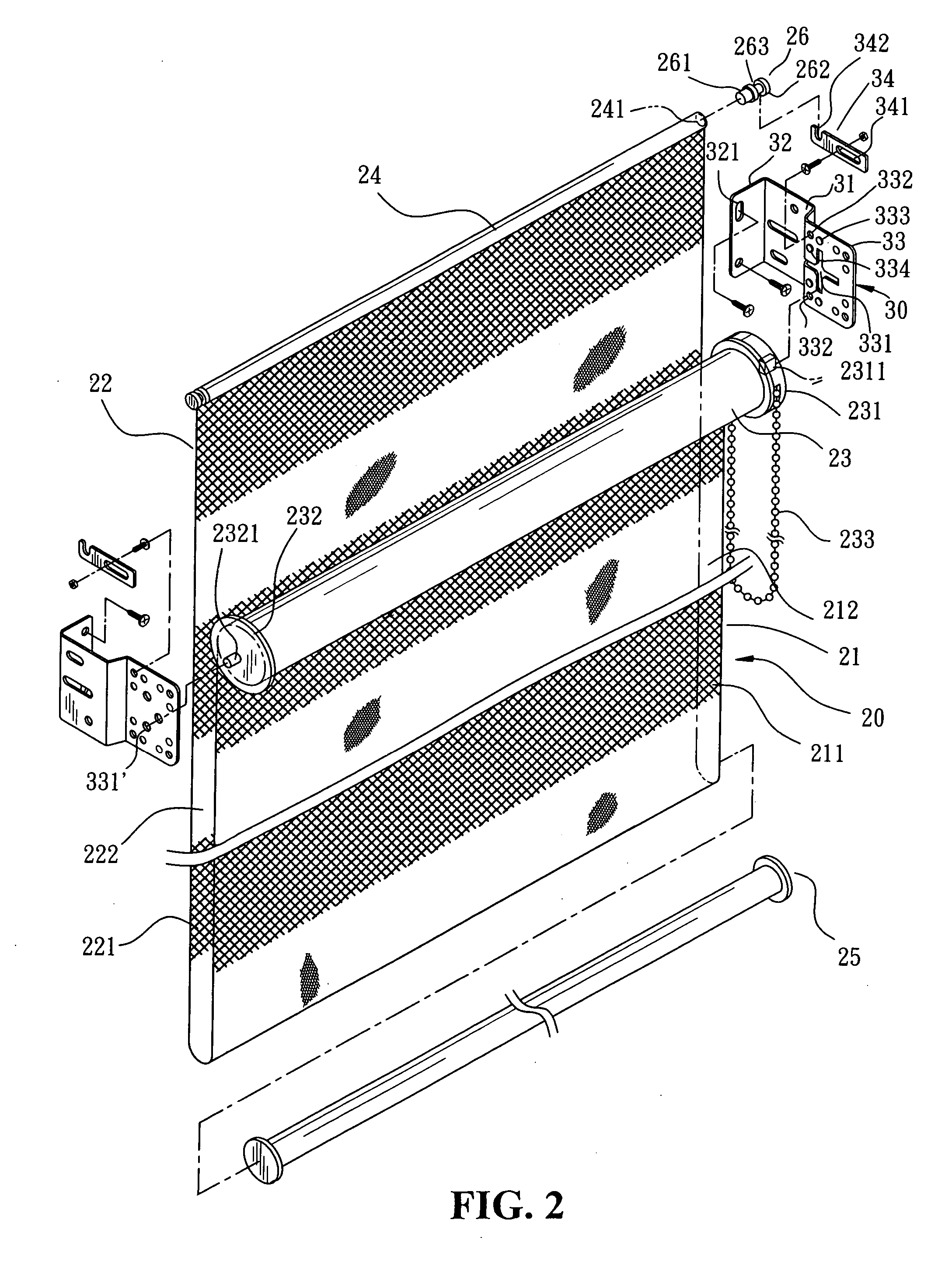
[0013] Please refer to FIG. 2 showing an exploded perspective view of the present invention. The present invention is related to a window blind structure, comprising a blind body 20 and a set of left and right support bracket 30. The blind body 20 is extended and fold into a U-shaped configuration to provide a first shade section 21 and a second shade section 22 each made up of a plurality of light-permeable areas 211, 221 and light-shading areas 212, 222 alternatively arranged one to another at the surface thereon respectively. At both end edges of the blind body 20 are respectively attached a winding shaft 23 and a hanging rod 24, and a rod-like counterweight object 25 is accommodated into the bending area of the blind body 20. A covering 231 with a positioning rib 2311 protruding thereon, and a linkage body 232 with a pivoting post 2321 extending thereon are respectively mounted to both end edges of the winding shaft 23 thereof. An operational element 233 like a beaded chain is p...


PUM


Abstract

A window blind structure comprises a blind body and a set of left/right support brackets wherein the blind body is folded into a U shape with a winding shaft and a hanging rod respectively attached at both end edges thereto, and a counterweight object accommodated into the bending area for even suspension of the blind body thereby. Each left/right support bracket has a grooved area with a fixing surface at one side, and an extension portion at the other side wherein one extension portion has crosswise retaining recesses cut thereon, and the other pivoting holes disposed thereon for holding the winding shaft there-between. Around four side corners of each extension portion are respectively disposed a thru-hole accompanied by first and second positioning blocks to match with an adjusting support member that can flexibly change the direction of assembly, achieving more versatile and convenient assembly of the left/right support brackets thereby.

Description

BACKGROUND OF THE INVENTION [0001] The present invention is related to a window blind structure, comprising a blind body and a set of left and right support brackets wherein each left / right support bracket has a grooved area with a fixing surface at one side, and an extension portion at the other side; one extension portion has crosswise retaining recesses cut thereon, and the other has pivoting holes disposed thereon so as to hold a winding shaft there-between, and around four side corners of each extension portion are respectively disposed a thru-hole accompanied by a set of first and second positioning blocks to cooperatively work with an adjusting support member that can flexibly change the direction of assembly for the mounting of a hanging rod thereon, achieving more versatile and convenient assembly of the left / right support brackets thereby. [0002] Please refer to FIG. 1 showing an assembled perspective view of a conventional blind structure. A conventional blind structure i...

Claims


Application Information

Patent Timeline
IPC IPC(8): A47H1/00
CPCA47H23/06E06B9/42E06B2009/2405
Inventor NIEN, LESLIE
Owner NIEN LESLIE
Why Eureka
Try Eureka