
Pump and method

a technology of pump and pump body, applied in the field of pumps, can solve problems such as devices that are not suitable for other environments

Inactive Publication Date: 2007-04-19
PRATT & WHITNEY CANADA CORP
View PDF27 Cites 6 Cited by
  • Summary
  • Abstract
  • Description
  • Claims
  • Application Information

AI Technical Summary

Benefits of technology

The pump achieves high flow rates and pressures with reduced energy loss, operates efficiently at high speeds, and eliminates the need for bearings, offering improved reliability and lower costs while maintaining laminar flow for effective liquid circulation.

Problems solved by technology

While perhaps suited for pumping blood and other low speed and low pressure application, these devices are unsuitable for other environments, particularly where high speed and high pressures are desired.

Method used


Image

  • Pump and method
  • Pump and method
  • Pump and method

Examples


Embodiment Construction

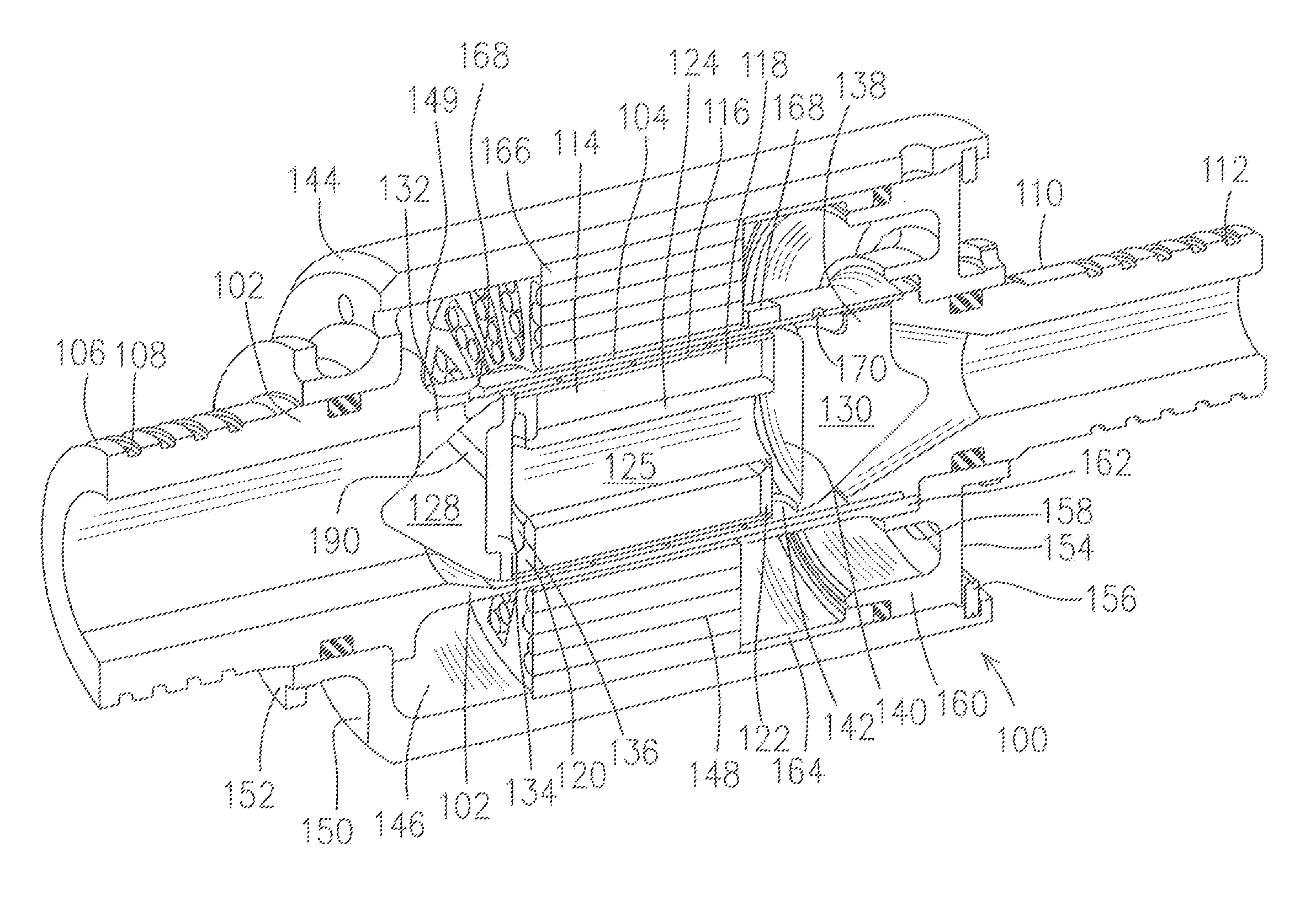
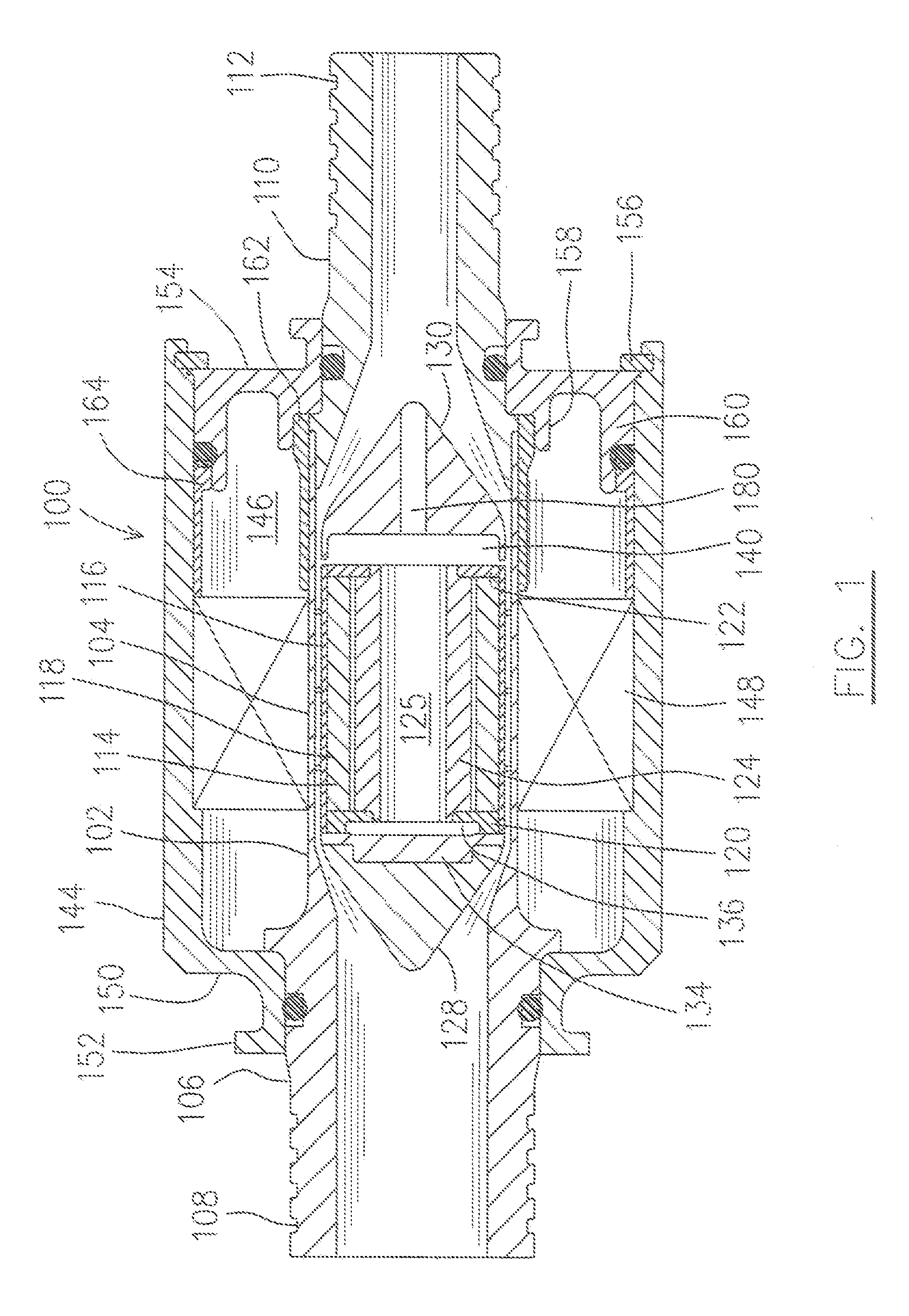
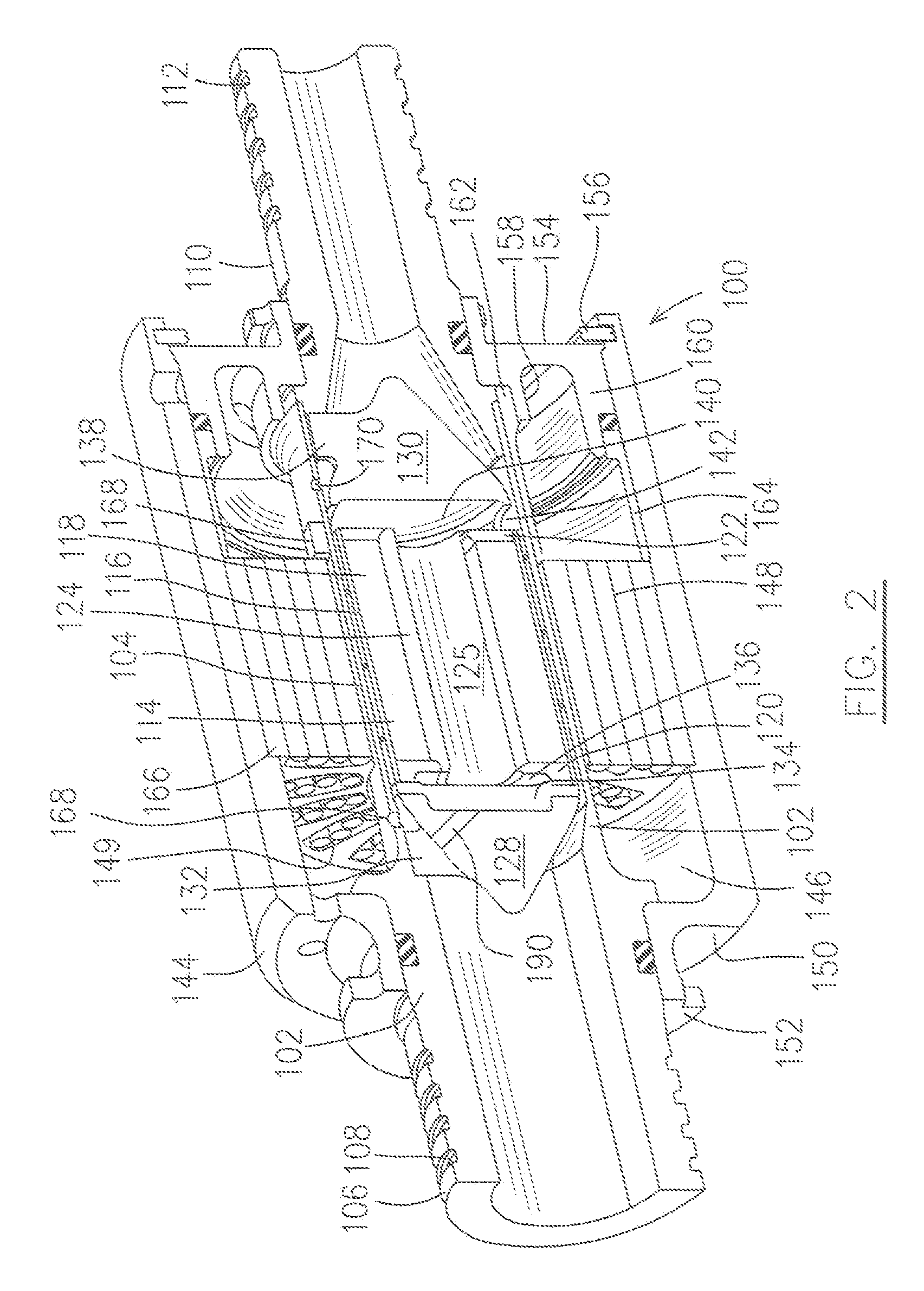
[0024] Referring to FIGS. 1, 2 and 4, a helix pump, generally indicated at numeral 100, is provided according to one preferred embodiment of the present invention.

[0025] The helix pump 100 includes a cylindrical housing 102 having at one end a working conduit 104, a pump inlet 106, and pump outlet 110. The housing 102, or at least the working conduit 104 are made of non-metal material, for example, a plastic, ceramic or other electrically non-conductive material, so that eddy currents are not induced by the alternating magnetic field of the stator and rotor system. Preferably, in addition to being non-conductive, the inner wall of conduit 104 is smooth, and not laminated, to thereby provide sealing capability and low friction with the rotor, as will be described further below. Connection means, such as a plurality of annular grooves 108, are provided on pump inlet 106 for connection with an oil source such as an oil tank (not shown). The end of the working conduit 104 abuts a shoul...


PUM


Abstract

An anti-icing system comprises a pump and a circulation network, the pump pumping a liquid through the circulation network, wherein the pump is configured to generate heat during operation as a result of viscous shear in the pumped liquid, the heat being sufficient to provide a pre-selected anti-icing heat load to the liquid.

Description

[0001] This is a Continuation of Applicant's U.S. patent application Ser. No. 11 / 017797 filed on Dec. 22, 2004.FIELD OF THE INVENTION [0002] The present invention relates to a pump used for pumping liquid. BACKGROUND OF THE INVENTION [0003] Electrically driven helix-type pumps are known. Permanent magnet pumps are also known. for example, a centrifugal blood pump is disclosed in U.S. Pat. No. 5,049,134 and an axial blood pump is disclosed in U.S. Pat. No. 5,692,882. In general, these and other helix pumps rely on friction or fluid dynamic lift to move fluid axially though the pump. That is, although the helix rotates, the liquid is rotationally relatively stationary as it moves axially along the length of the pump. While perhaps suited for pumping blood and other low speed and low pressure application, these devices are unsuitable for other environments, particularly where high speed and high pressures are desired. Room for improvement is therefore available. SUMMARY OF THE INVENTIO...

Claims


Application Information

Patent Timeline
Patent Type & Authority Applications(United States)
IPC IPC(8): F04B17/00
CPCF04D3/02F04D13/0606F04D29/047F04D29/181
Inventor DOOLEY, KEVIN ALLAN
Owner PRATT & WHITNEY CANADA CORP
Learn More