Endoluminal delivery assembly

a technology of endoluminal and assembly, which is applied in the field of endoluminal delivery assembly, can solve the problems of occlusion of one or more, thoracic arch could have serious consequences, and the final rotational position of the stent may not be fully known

Active Publication Date: 2007-04-19
COOK MEDICAL TECH LLC +1
View PDF12 Cites 91 Cited by
  • Summary
  • Abstract
  • Description
  • Claims
  • Application Information

AI Technical Summary

Problems solved by technology

Major branch vessels extend from the thoracic arch and occlusion of one or more of these upon placement of a stent graft in the thoracic arch could have serious consequences.
It is known to retain the proximal and distal ends of a stent graft onto a deployment device to fac

Method used


Image

  • Endoluminal delivery assembly
  • Endoluminal delivery assembly
  • Endoluminal delivery assembly

Examples


Embodiment Construction

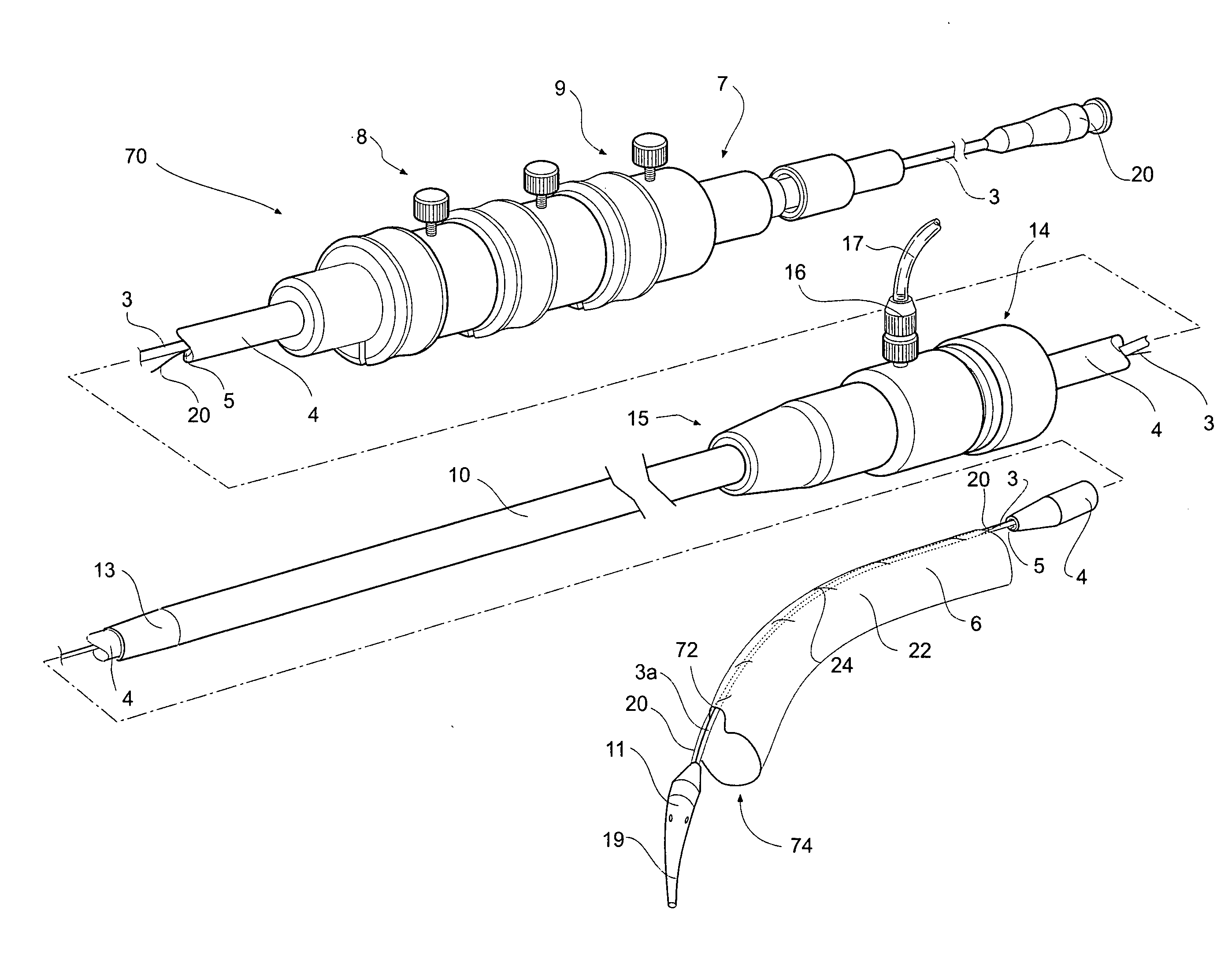
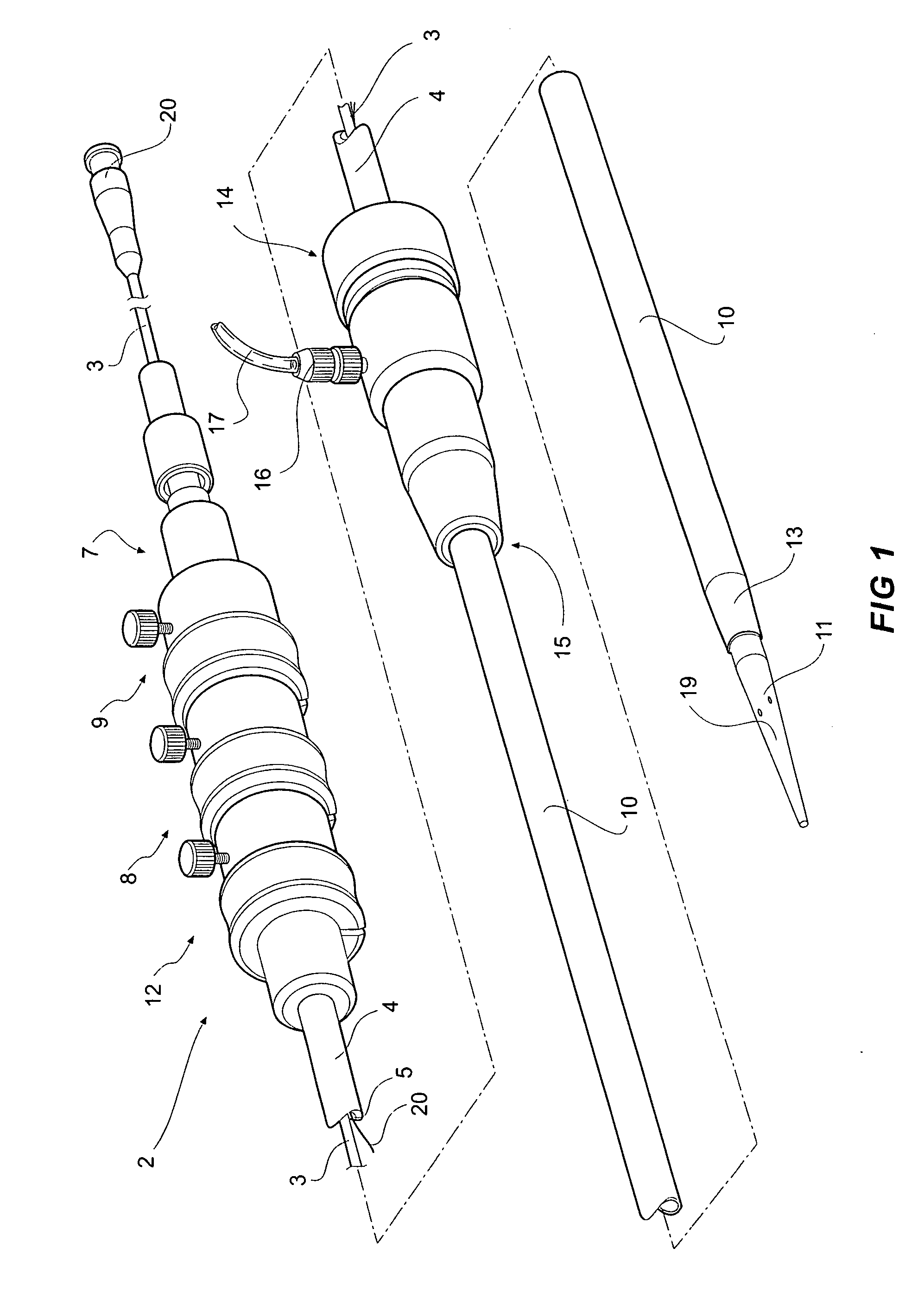
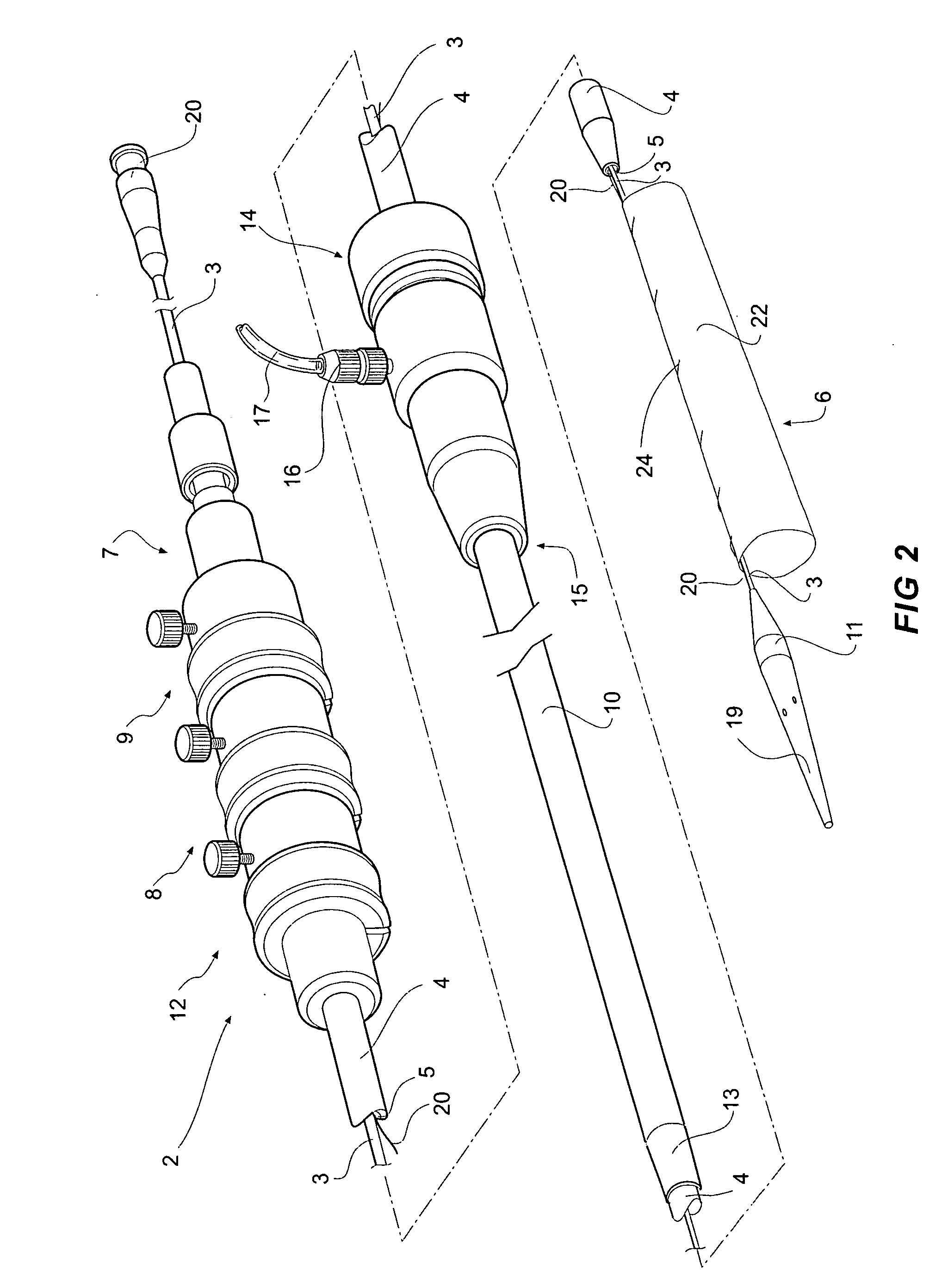
[0044]FIGS. 1, 2 and 3A and 3B depict a delivery device 2 according to one embodiment of the invention. The delivery device 2 has a guide wire catheter 3 which extends from a distal handle 7 to a proximal tapered nose cone dilator 11 longitudinally through a passageway or lumen 5 of a delivery catheter 4 which is connected to the handle 7 at its distal end. An introducer sheath 10 fits coaxially around the delivery catheter 4 and extends from a tapered proximal end 13 which optionally includes a radiopaque marker to a connector valve and manipulator 14 attached about distal end 15 of the sheath. The introducer sheath 10 extends proximally to the nose cone dilator 11 and covers the stent graft 6 during introduction of the deployment device into a patient and is withdrawn distally to expose the stent graft 6 during deployment when the deployment device is in a selected position within the vasculature of a patient. The stent graft or implantable device 6 is carried on the guide wire ca...


PUM


Abstract

A stent graft delivery system in which a stent graft ( 6 ) is retained on a delivery device ( 2 ) such that a longitudinal portion of the stent graft is releasably retained on the delivery device to bend therewith. The delivery device ( 2 ) has a guide wire catheter ( 3 ) and the stent graft is retained onto the guide wire catheter by a release wire ( 24 ) which can be withdrawn. The release wire is wound around the guide wire catheter and through the stent graft or suture loops engage around the guide wire catheter and release wire.

Description

CROSS-REFERENCE TO RELATED APPLICATIONS [0001] This application claims priority of provisional application Ser. No. 60 / 719,081, filed Sep. 21, 2005.TECHNICAL FIELD [0002] This invention relates to a delivery device or deployment device for intraluminal or endovascular delivery of a stent graft. BACKGROUND OF THE INVENTION [0003] The invention will be discussed generally with respect to deployment of a stent graft into the thoracic aorta but is not so limited and may apply to deployment into other body lumens. [0004] It is important when delivering a stent graft by intraluminal or endovascular methods to know exactly where the device is in the vasculature particularly in relation to branch vessels which could be adversely occluded by placement of the stent graft. To avoid occlusion there have been proposed fenestrations along the length of a stent graft and scalloping at the proximal and distal ends of the stent graft to allow flow from a main vessel to a branch vessel through the fe...

Claims


Application Information

Patent Timeline
IPC IPC(8): A61F2/84A61F2/06
CPCA61F2/07A61F2/954A61F2002/061A61M25/0152A61F2002/9511A61F2002/9517A61F2002/9665A61F2002/9505
Inventor GREENBERG, ROY K.HARTLEY, DAVID ERNEST
Owner COOK MEDICAL TECH LLC
Why Eureka
Try Eureka