
Internal combustion engine with auxiliary combustion chamber

a technology of internal combustion engine and auxiliary combustion chamber, which is applied in the direction of internal combustion piston engine, combustion engine, machine/engine, etc., can solve the problems of abnormal combustion, temperature rise of rapid accumulation of heat at the tip portion of the partition wall

Inactive Publication Date: 2007-04-26
NISSAN MOTOR CO LTD
View PDF19 Cites 13 Cited by
  • Summary
  • Abstract
  • Description
  • Claims
  • Application Information

AI Technical Summary

Benefits of technology

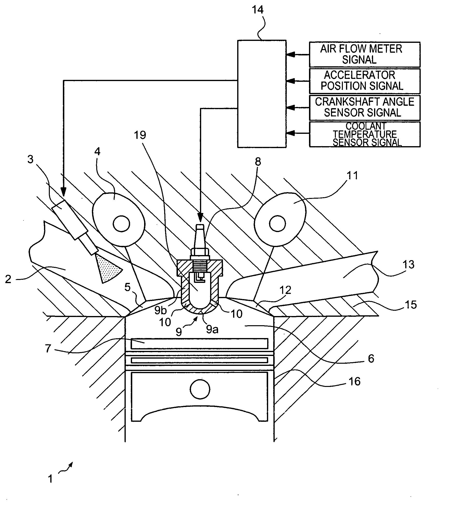
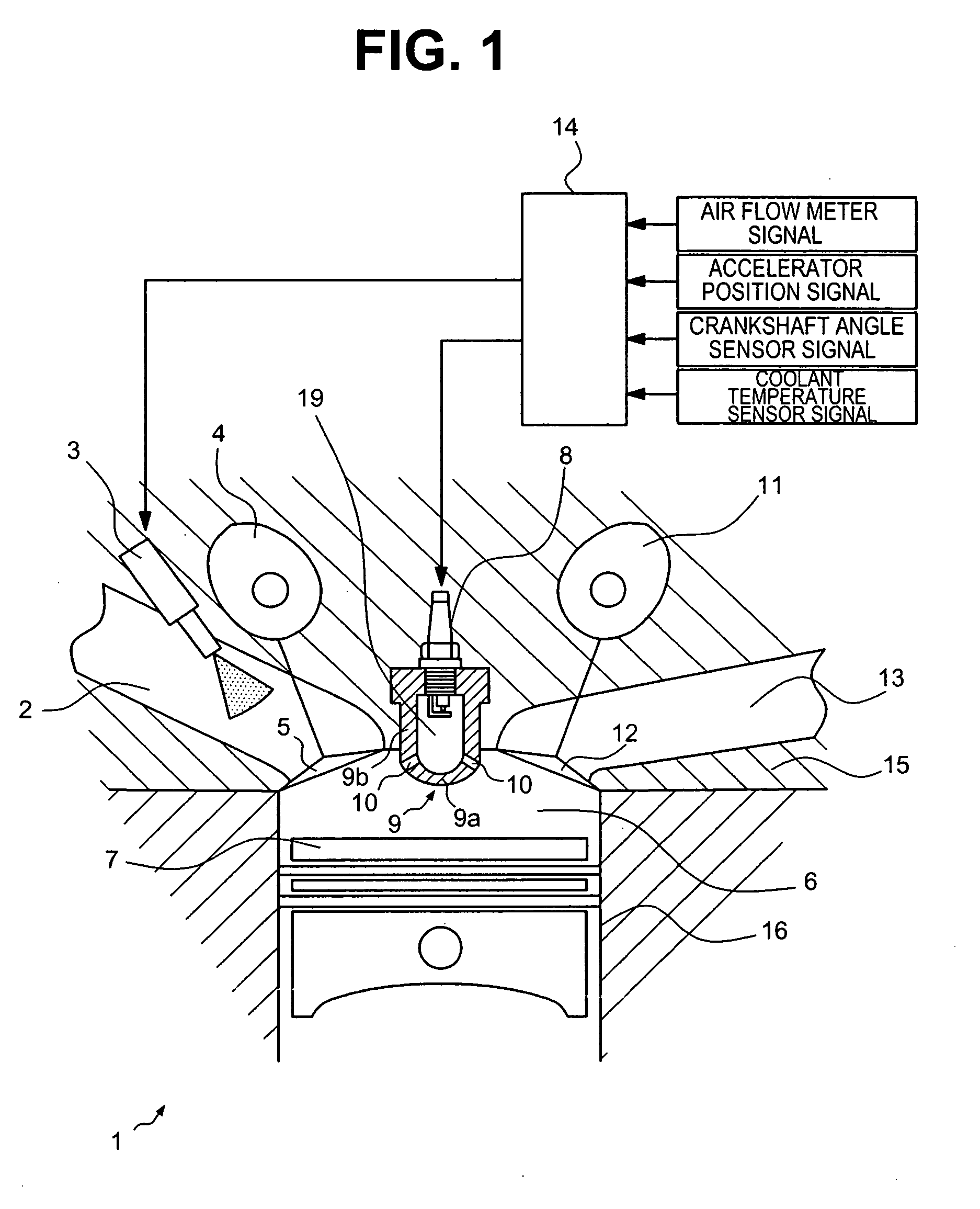
[0010] Accordingly, one object of the present invention is to provide an internal combustion engine with auxiliary combustion chamber that is configured to prevent abnormal combustion caused by premature ignition and the like in the high load driving region.

Problems solved by technology

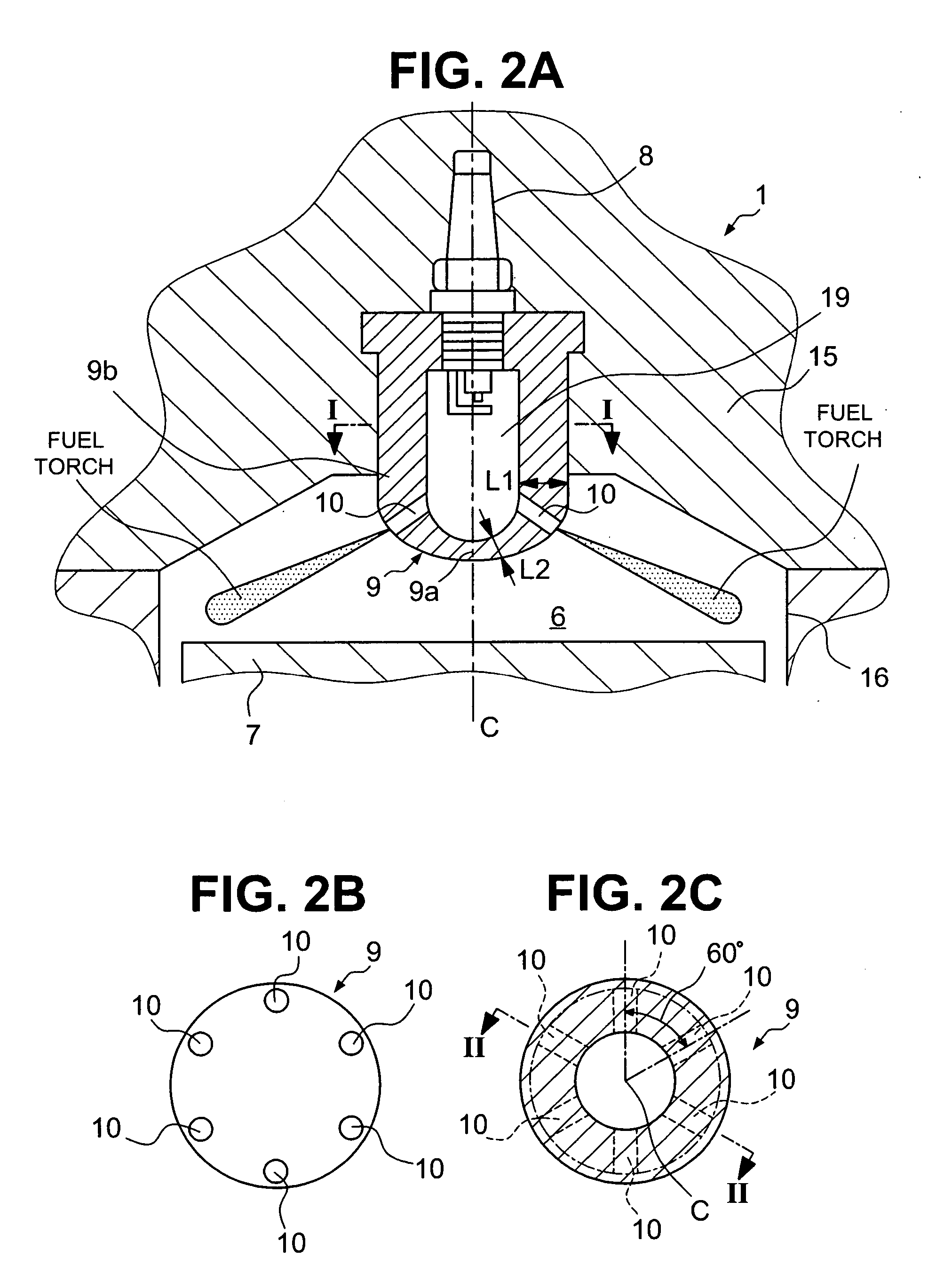
However, with the conventional internal combustion engine with the auxiliary combustion chamber as described in the above mentioned reference, heat accumulates quickly at the tip portion of the partition wall because the tip portion with the relatively large wall thickness has relatively large thermal capacity which prevents an efficient thermal exchange between fresh intake air and the tip portion of the partition wall.
As a result, the temperature of the tip portion of the partition wall rises because heating and cooling do not come to equilibrium.
Therefore, there is a risk that abnormal combustion occurs when the high load driving condition continues in the conventional internal combustion engine because temperature at the tip portion, in particular, of the partition wall becomes high, and premature ignition of the air-fuel mixture within the main combustion chamber takes place.

Method used


Image

  • Internal combustion engine with auxiliary combustion chamber
  • Internal combustion engine with auxiliary combustion chamber
  • Internal combustion engine with auxiliary combustion chamber

Examples


second embodiment

[0045] Referring now to FIGS. 3A to 3C, an internal combustion engine 1′ with an auxiliary combustion chamber 19′ in accordance with a second embodiment will now be explained. The structure of the internal combustion engine 1′ of the second embodiment is identical to the structure of the internal combustion engine 1 of the first embodiment, except for the structure of an auxiliary chamber partition wall 9′ that defines an auxiliary chamber 19′. In view of the similarity between the first and second embodiments, the parts of the second embodiment that are identical to the parts of the first embodiment will be given the same reference numerals as the parts of the first embodiment. Moreover, the descriptions of the parts of the internal combustion engine 1′ other than the auxiliary chamber partition wall 9′ of the second embodiment that are identical to the parts of the first embodiment will be omitted for the sake of brevity. The parts of the second embodiment that differ from the par...

third embodiment

[0054] Referring now to FIGS. 4A to 4C, an internal combustion engine 1″ with an auxiliary combustion chamber 19″ in accordance with a third embodiment will now be explained. The structure of the internal combustion engine 1″ of the third embodiment is identical to the structure of the internal combustion engine 1 of the first embodiment, except for the structure of an auxiliary chamber partition wall 9″ that defines an auxiliary chamber 19″. In view of the similarity between the first, second and third embodiments, the parts of the third embodiment that are identical to the parts of the first and second embodiments will be given the same reference numerals as the parts of the first embodiment. Moreover, the descriptions of the parts of the internal combustion engine 1″ other than the auxiliary chamber partition wall 9″ of the third embodiment that are identical to the parts of the first and second embodiments will be omitted for the sake of brevity. The parts of the third embodimen...

fourth embodiment

[0067] Referring now to FIGS. 5A to 5C, an internal combustion engine 1′″ with auxiliary combustion chamber in accordance with a fourth embodiment will now be explained. The structure of the internal combustion engine 1′″ of the fourth embodiment is identical to the structure of the internal combustion engine 1 of the first embodiment, except for the structure of an auxiliary chamber partition wall 9′″ that defines an auxiliary chamber 19′″. In view of the similarity between the first through fourth embodiments, the parts of the internal combustion engine 1′″ other than the auxiliary chamber partition wall 9′″ of the fourth embodiment that are identical to the parts of the first through third embodiments will be given the same reference numerals as the parts of the first through third embodiments. Moreover, the descriptions of the parts of the fourth embodiment that are identical to the parts of the first through third embodiments will be omitted for the sake of brevity. The parts o...


PUM


Abstract

An internal combustion engine is provided that basically comprises a cylinder block, a cylinder head, a piston, an auxiliary chamber partition wall and a spark plug. The auxiliary chamber partition wall is coupled to the cylinder head and extending toward the main chamber to form an auxiliary combustion chamber inside an area enclosed by the auxiliary chamber partition wall. The auxiliary chamber partition wall has at least one jet aperture through which the auxiliary combustion chamber fluidly communicates with the main combustion chamber. A tip portion of the auxiliary chamber partition wall that faces toward the piston has a smaller wall thickness than other portion of the auxiliary chamber partition wall.

Description

CROSS-REFERENCE TO RELATED APPLICATIONS [0001] This application claims priority under 35 U.S.C. §119 to Japanese Patent Application No.2005-308019, filed on Oct. 24, 2005. The entire disclosure of [0002] Japanese Patent Application No.2005-308019 is hereby incorporated herein by reference. BACKGROUND OF THE INVENTION [0003] 1. Field of the Invention [0004] The present invention relates to an internal combustion engine with auxiliary combustion chamber. More specifically, the present invention relates to an internal combustion engine with auxiliary combustion chamber configured to prevent occurrences of premature ignition. [0005] 2. Background Information [0006] In a conventional internal combustion engine provided with an auxiliary combustion chamber, there are problems that engine knocking is more likely to occur when temperature level inside a combustion chamber rises and an effective combustion control cannot be performed. Therefore, in such a conventional internal combustion eng...

Claims


Application Information

Patent Timeline
Patent Type & Authority Applications(United States)
IPC IPC(8): F02B19/00F02B19/18
CPCF02B19/12F02B19/16Y02T10/125Y02T10/12
Inventor SHIRAISHI, TAISUKEKAKUHO, AKIHIKOTAKAHASHI, EIJINAGAMINE, MORIHIRO
Owner NISSAN MOTOR CO LTD
Learn More