Piston of engine

a technology of pistons and pistons, which is applied in the direction of combustion-air/fuel-air treatment, machines/engines, fuel air intakes, etc., can solve the problems of abnormal combustion, reduced durability of engines, and combustion noise, so as to reduce the temperature of combustion engines and reduce the temperature in the combustion chamber , the effect of preventing abnormal combustion

Inactive Publication Date: 2013-04-02
HYUNDAI MOTOR CO LTD +1
View PDF12 Cites 3 Cited by
  • Summary
  • Abstract
  • Description
  • Claims
  • Application Information

AI Technical Summary

Benefits of technology

[0015]Various aspects of the present invention are directed to provide for a piston of an engine that can decrease the temperature in the combustion engine by cooling around the combustion engine without changing the material of the cylinder head, taking a method of decreasing the temperature in the combustion chamber in ways of preventing abnormal combustion.
[0027]A piston cooling jet may be disposed to the cylinder block and supply oil to the bottom surface of the crown of the piston to increase cooing efficiency.

Problems solved by technology

On the other hand, in an engine equipped with a turbocharger, when the compression ratio in combustion chamber 4 is excessively increased by excessive supply, abnormal combustion, such as knocking, is caused by rapid mix with excessive air around the top dead center in combustion.
Therefore, the main parts of the engine are damaged by high temperature and pressure due to the abnormal combustion, such as damage to the intake / exhaust valves, breakage and sticking of the piston, and crack in the valve bridge of the cylinder head, which decreases durability of the engine.
Further, there was a problem in that combustion noise is caused by the abnormal combustion when a vehicle starts or changes the speed.
Further, there was a problem in that abnormal vibration is caused in the engine by the abnormal combustion.

Method used


Image

  • Piston of engine
  • Piston of engine
  • Piston of engine

Examples


Embodiment Construction

[0041]Reference will now be made in detail to various embodiments of the present invention(s), examples of which are illustrated in the accompanying drawings and described below. While the invention(s) will be described in conjunction with exemplary embodiments, it will be understood that present description is not intended to limit the invention(s) to those exemplary embodiments. On the contrary, the invention(s) is / are intended to cover not only the exemplary embodiments, but also various alternatives, modifications, equivalents and other embodiments, which may be included within the spirit and scope of the invention as defined by the appended claims.

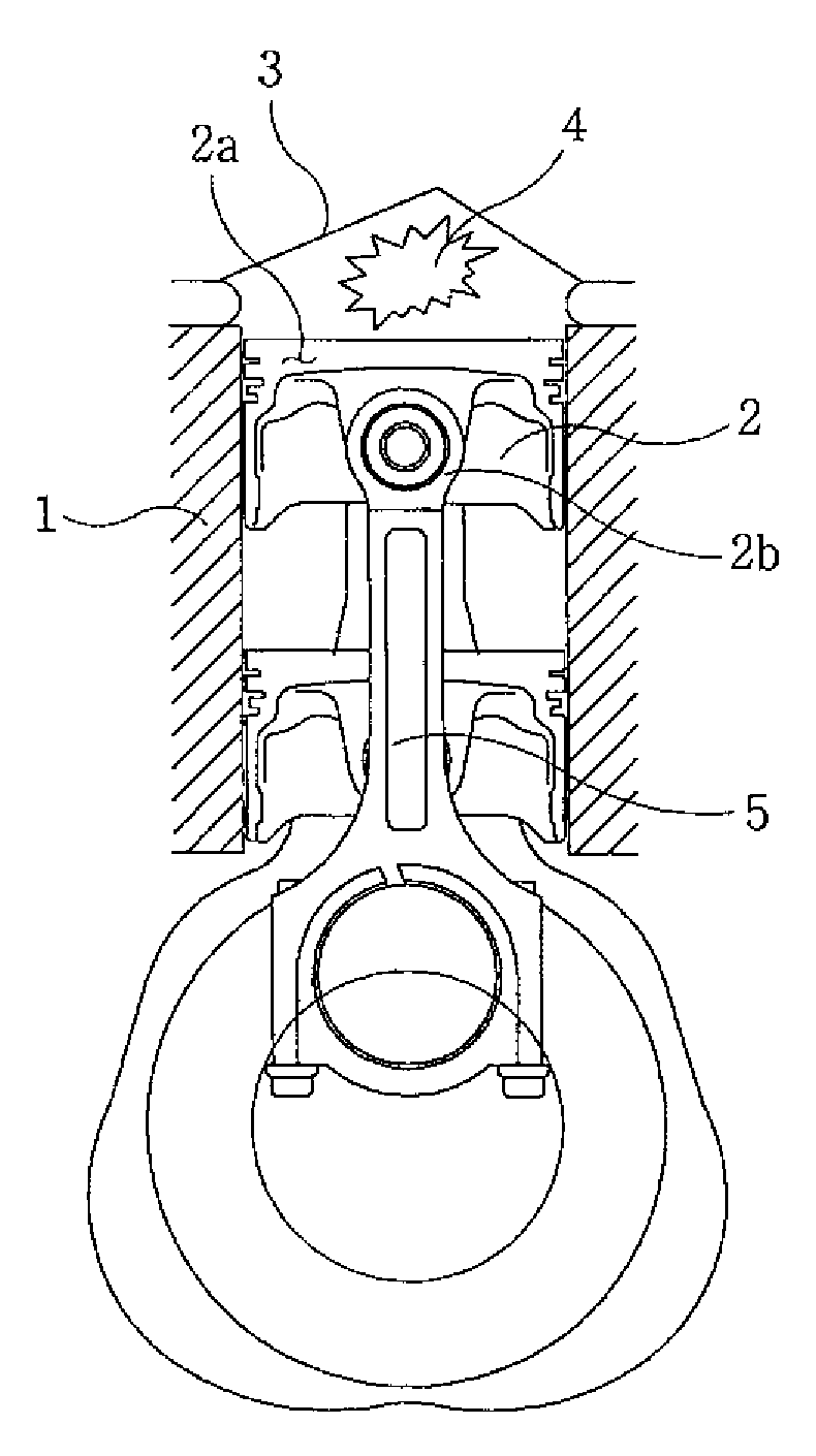
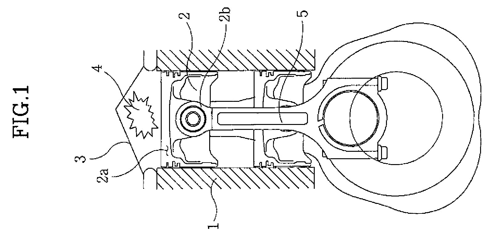
[0042]FIG. 3 is a view illustrating the configuration of an engine equipped with a piston according to various embodiments of the present invention, in which a cylinder block 1, a piston 2, a cylinder head 3, and a connecting rod 5 are simply shown.

[0043]As known in the art, piston 2 is disposed in cylinder block 1, connecting rod 5 i...


PUM


Abstract

A piston cooling apparatus of an engine may include a combustion chamber formed between a piston disposed in a cylinder block and a cylinder head disposed on the cylinder block, wherein a surface area-enlarging portion is formed inside the piston on bottom surface of a crown of the piston.

Description

CROSS-REFERENCE TO RELATED APPLICATIONS[0001]The present application claims priority to Korean Patent Application Number 10-2008-0052923 filed Jun. 5, 2008, the entire contents of which application is incorporated herein for all purposes by this reference.BACKGROUND OF THE INVENTION[0002]1. Field of the Invention[0003]The present invention relates to a piston of an engine, particularly a piston of an engine that reduces damage, noise, vibration due to abnormal combustion by reducing the temperature of a combustion chamber through smooth cooling.[0004]2. Description of Related Art[0005]As shown in FIG. 1, a combustion chamber 4 of an engine is formed by the upper surface of a piston 2 disposed in a cylinder block 1 and a cylinder head 3 disposed on a gasket on the upper surface of the cylinder block 1 (a recessed upper surface of the combustion that covers the upper portion of a cylinder bore is formed on the lower surface of the cylinder head 3).[0006]Piston 2 is connected to a cran...

Claims


Application Information

Patent Timeline
Patent Type & Authority Patents(United States)
IPC IPC(8): F01P5/10
CPCF02F3/16F02F3/20F02F3/22
Inventor KO, GABSEOK
Owner HYUNDAI MOTOR CO LTD
Why Eureka
Try Eureka