
A control device of an internal combustion engine and a control method thereof

a control device and internal combustion engine technology, applied in the direction of electric control, machines/engines, mechanical equipment, etc., can solve the problems of easy occurrence of abnormal combustion and inability to prevent abnormal combustion, and achieve the effect of reducing the upper limit of engine torqu

Active Publication Date: 2017-01-12
NISSAN MOTOR CO LTD
View PDF3 Cites 3 Cited by
  • Summary
  • Abstract
  • Description
  • Claims
  • Application Information

AI Technical Summary

Benefits of technology

The present invention relates to a control device for internal combustion engines. The technical effect of the invention is to prevent abnormal combustion caused by self-ignition, which occurs due to high engine water temperature. The control device calculates an abnormal combustion prevention torque and controls the engine torque to prevent it from being equal to or higher than the prevention torque. This prevents damage to the engine and ensures safe operation.

Problems solved by technology

However, a presence of an abnormal combustion caused by self-ignition was found, which abnormal combustion tends to happen easily at a lower engine water temperature, due to a cause different from such a general cause of the occurrence of self-ignition.
Such an abnormal combustion cannot be prevented even if the upper limit of the engine torque is reduced with the increase in the engine water temperature, as in the conventional cases.

Method used


Image

  • A control device of an internal combustion engine and a control method thereof
  • A control device of an internal combustion engine and a control method thereof
  • A control device of an internal combustion engine and a control method thereof

Examples


first embodiment

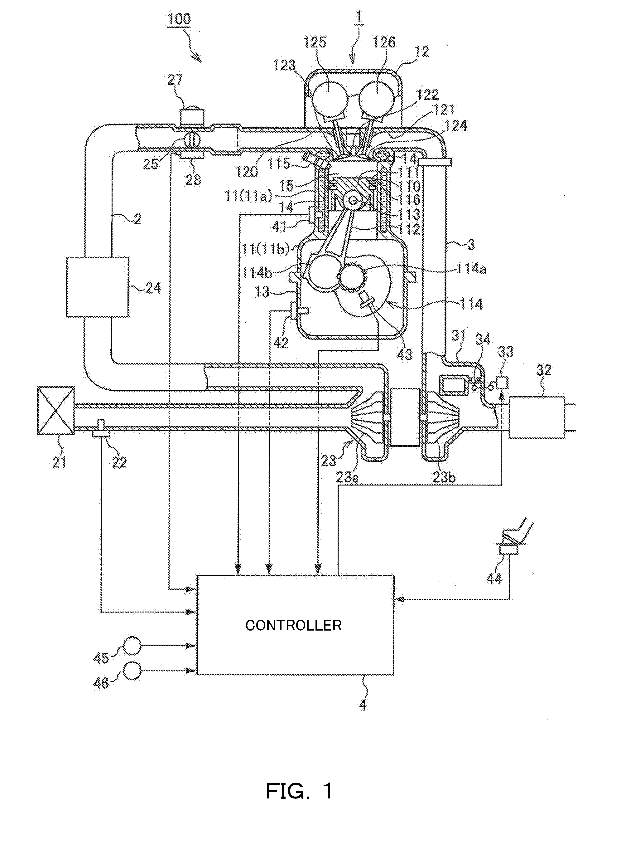
[0020]FIG. 1 is a schematic view of a control device 100 of a spark-ignition type internal combustion engine (hereinafter, called “engine”) 1, according to a first embodiment of the present invention.

[0021]The control device 100 of the engine 1 includes an engine 1, an intake passage 2 through which air taken into the engine 1 passes (hereinafter, called “intake air”) flows, an exhaust passage 3 through which combustion gas discharged from the engine 1 (hereinafter, called “exhaust air”) flows, and a controller 4.

[0022]The engine 1 includes a cylinder block 11, a cylinder head 12, an oil pan 13, and a water jacket 14.

[0023]The cylinder block 11 includes a cylinder section 11a and a crank case section 11b.

[0024]The cylinder section 11a has a plurality of cylinders 110 formed therein, and is attached with a fuel injection valve 115 that injects fuel directly into a combustion chamber 15. The cylinder 110 houses a piston 111 therein; the piston 111 reciprocates inside the cylinder 110...

second embodiment

[0102]Next describes a second embodiment of the present invention. The present embodiment differs from the first embodiment in the calculation method of the correction value of the low temperature abnormal combustion prevention torque. The following describes mainly on this difference. Parts in the following embodiments that perform the same functions as in the aforementioned first embodiment are designated with identical reference signs, and any duplicating descriptions will be omitted as appropriate.

[0103]FIG. 10 is a flow chart describing a low temperature abnormal combustion prevention torque calculation process according to the second embodiment.

[0104]In step S31, the controller 4 carries out the same process as in the first embodiment.

[0105]In step S232, the controller 4 carries out a process for calculating a correction value of the low temperature abnormal combustion prevention torque, on the basis of the intake air temperature. Details on the correction value calculation pr...


PUM


Abstract

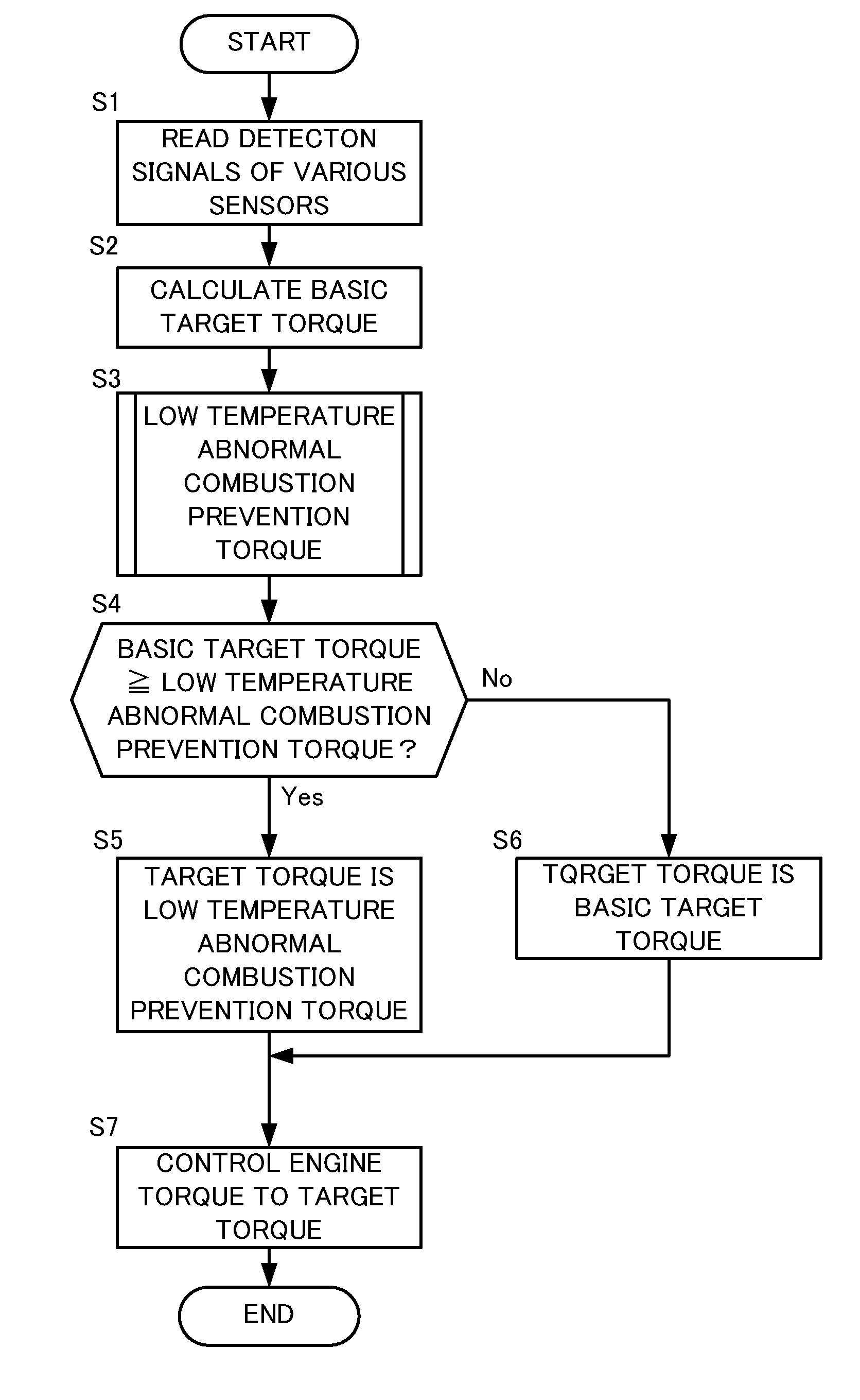
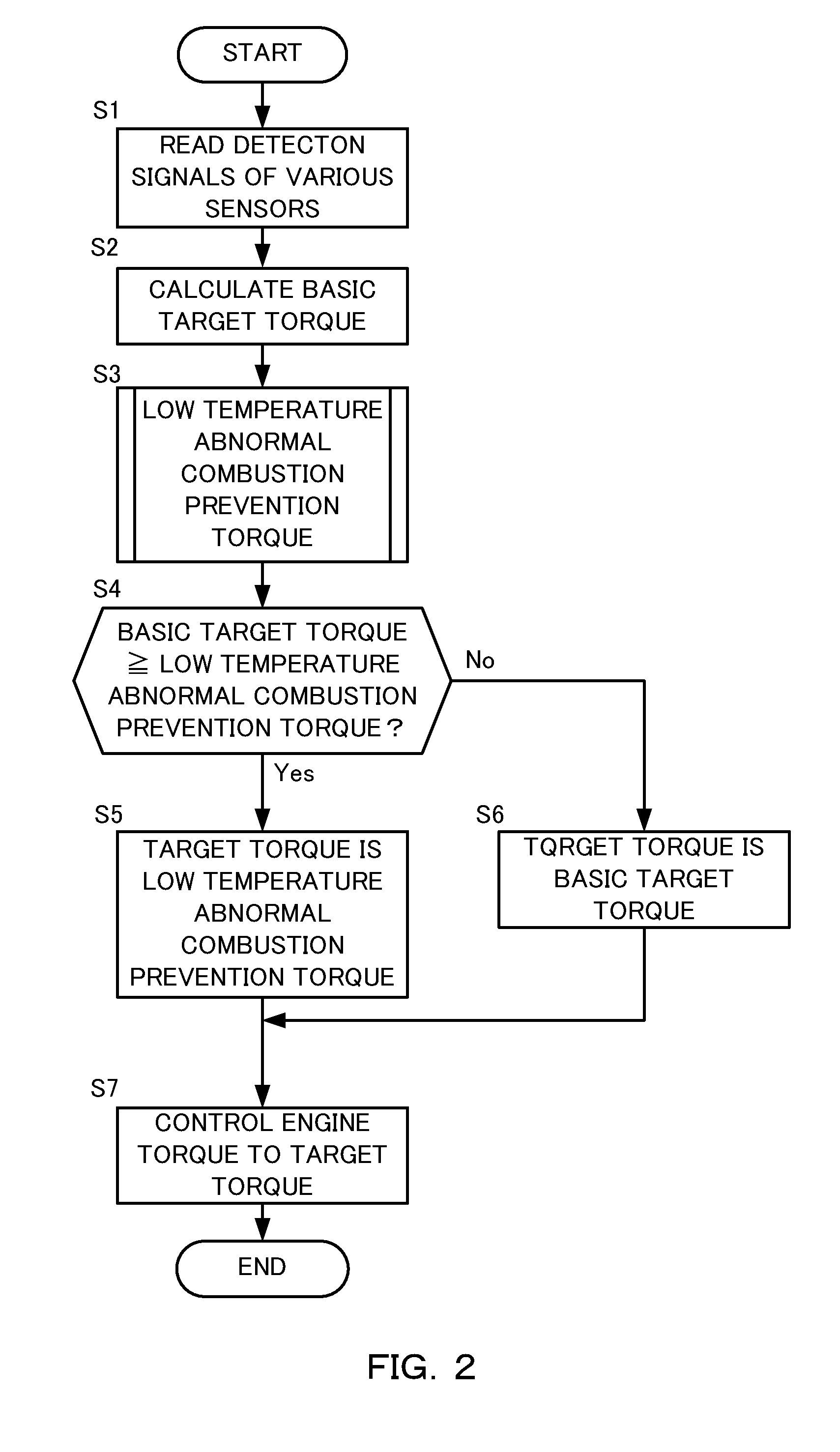
A control device of an internal combustion engine calculates an abnormal combustion prevention torque for preventing an abnormal combustion due to self-ignition whose heat source is a mixture of supplied fuel to the internal combustion engine and lubricant oil, on the basis of a cylinder wall temperature of the internal combustion engine or a temperature of a parameter in correlation with the cylinder wall temperature, and controls a torque of the internal combustion engine to prevent the torque of the internal combustion engine from becoming equal to or more than the abnormal combustion prevention torque.

Description

TECHNICAL FIELD[0001]The present invention relates to a control device of an internal combustion engine and a control method thereof.BACKGROUND ART[0002]JP2011-106411A discloses, as a conventional internal combustion engine control device, one that calculates an upper limit of an engine torque (intake air amount) on the basis of an intake pressure and engine rotation speed and further correcting this upper limit in accordance with an engine water temperature, to prevent an occurrence of abnormal combustion due to self-ignition of a fuel-air mixture.SUMMARY OF INVENTION[0003]In this conventional internal combustion engine control device, generally, as the engine water temperature increases, the temperature inside the cylinder also increases, which thus makes it easy for the fuel-air mixture to self-ignite. Accordingly, correction was made to reduce the upper limit of the engine torque with the increase in the engine water temperature.[0004]However, a presence of an abnormal combustio...

Claims


Application Information

Patent Timeline
IPC IPC(8): F02D41/10F02D35/02
CPCF02D41/107F02D35/025F02D2200/023F02D2200/0414F02D2200/101F02D41/22F02P5/152F02P5/153F02D23/00F02D41/047F02D41/068F02D35/027F02D2200/021F02D2200/1015F02D2250/18F02D2250/26F02D41/064Y02T10/12Y02T10/40
Inventor YAMANO, KENTAROUKAWASAKI, TAKAO
Owner NISSAN MOTOR CO LTD
Learn More