Top & bottom mount, heavy load supporting, girder clamp system

Inactive Publication Date: 2007-04-26
GULLEY WILLIAM F
View PDF0 Cites 5 Cited by
  • Summary
  • Abstract
  • Description
  • Claims
  • Application Information

AI Technical Summary

Benefits of technology

[0031] To release the clamping system of the first embodiment, the threaded rod is rotated in the reverse or screwing-out direction, causing the two, side gripping members to become further spaced apart, allowing them, along with the side support pieces, to be easily removed from the beam for further use in another installation.
[0032] Other drive mechanisms beside the more preferred threaded rod and the mating, threaded bore are possible, but the threaded rod & threaded bore approach for a mechanical drive mechanism is currently preferred in the first embodiment due to its compactness, strength, simplicity and economy and ease of m

Problems solved by technology

However, there are significant structural and application differences between the present invention and the Dietrich device, and it is particularly noted that the Dietrich device clamps to the low

Method used


Image

  • Top & bottom mount, heavy load supporting, girder clamp system
  • Top & bottom mount, heavy load supporting, girder clamp system
  • Top & bottom mount, heavy load supporting, girder clamp system

Examples


1st embodiment (top flange member connection only ; figs.1-8)

Initial, 1st Embodiment (Top Flange Member Connection Only; FIGS. 1-8)

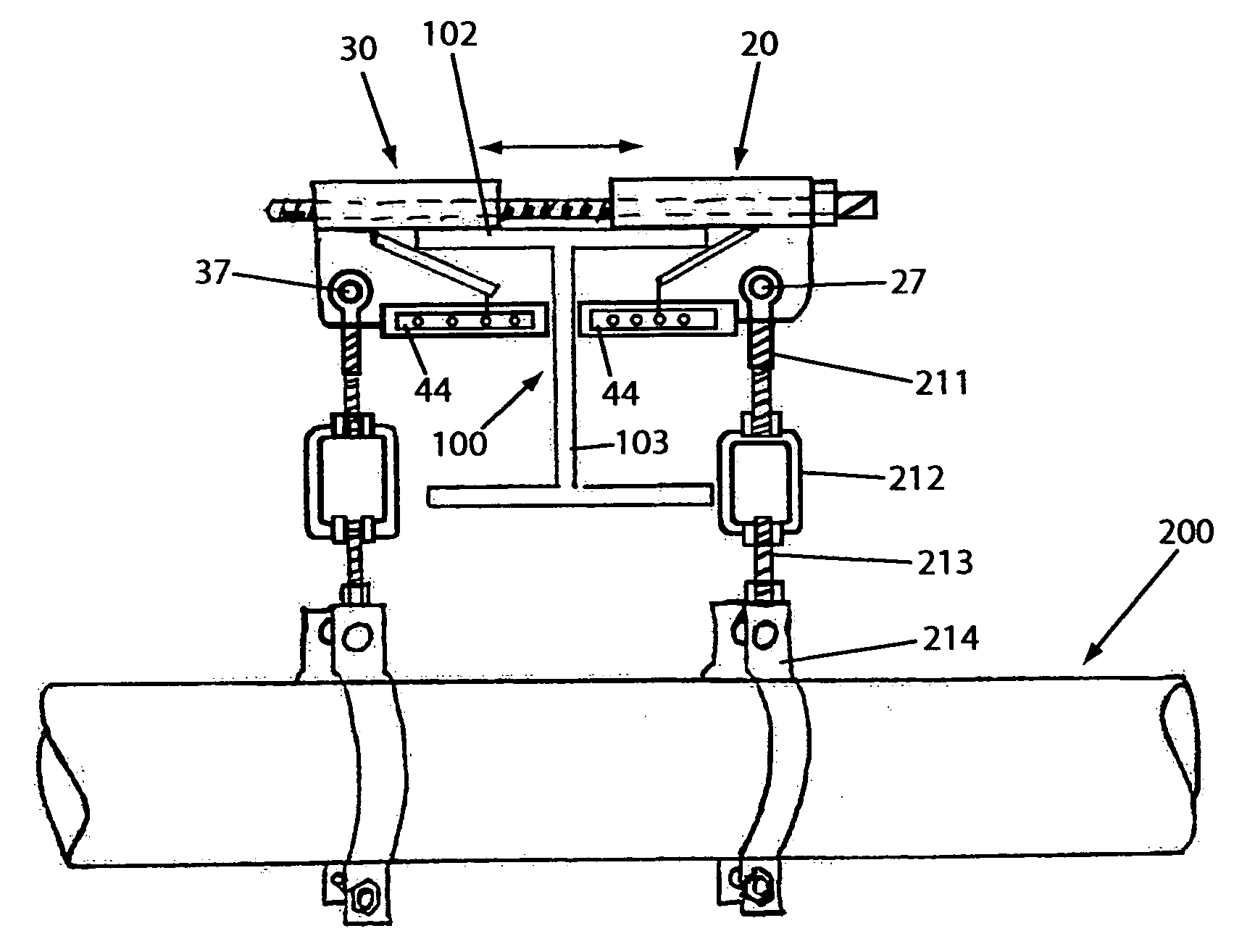
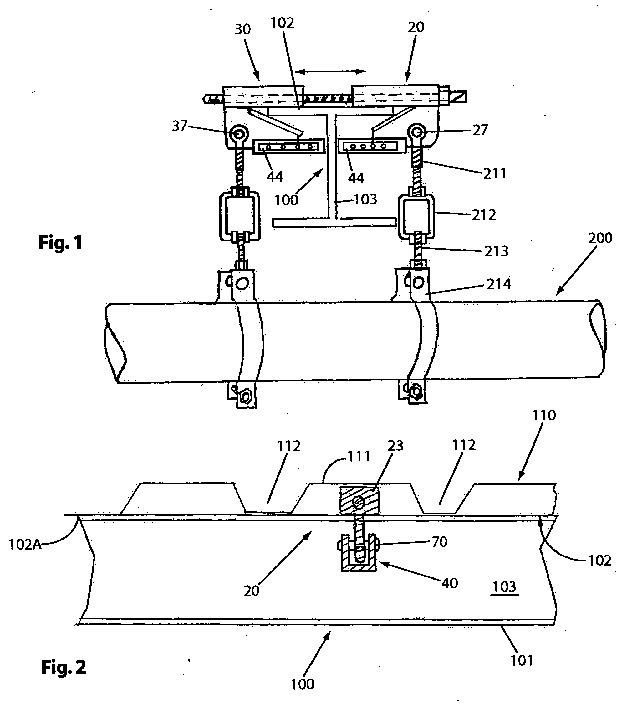
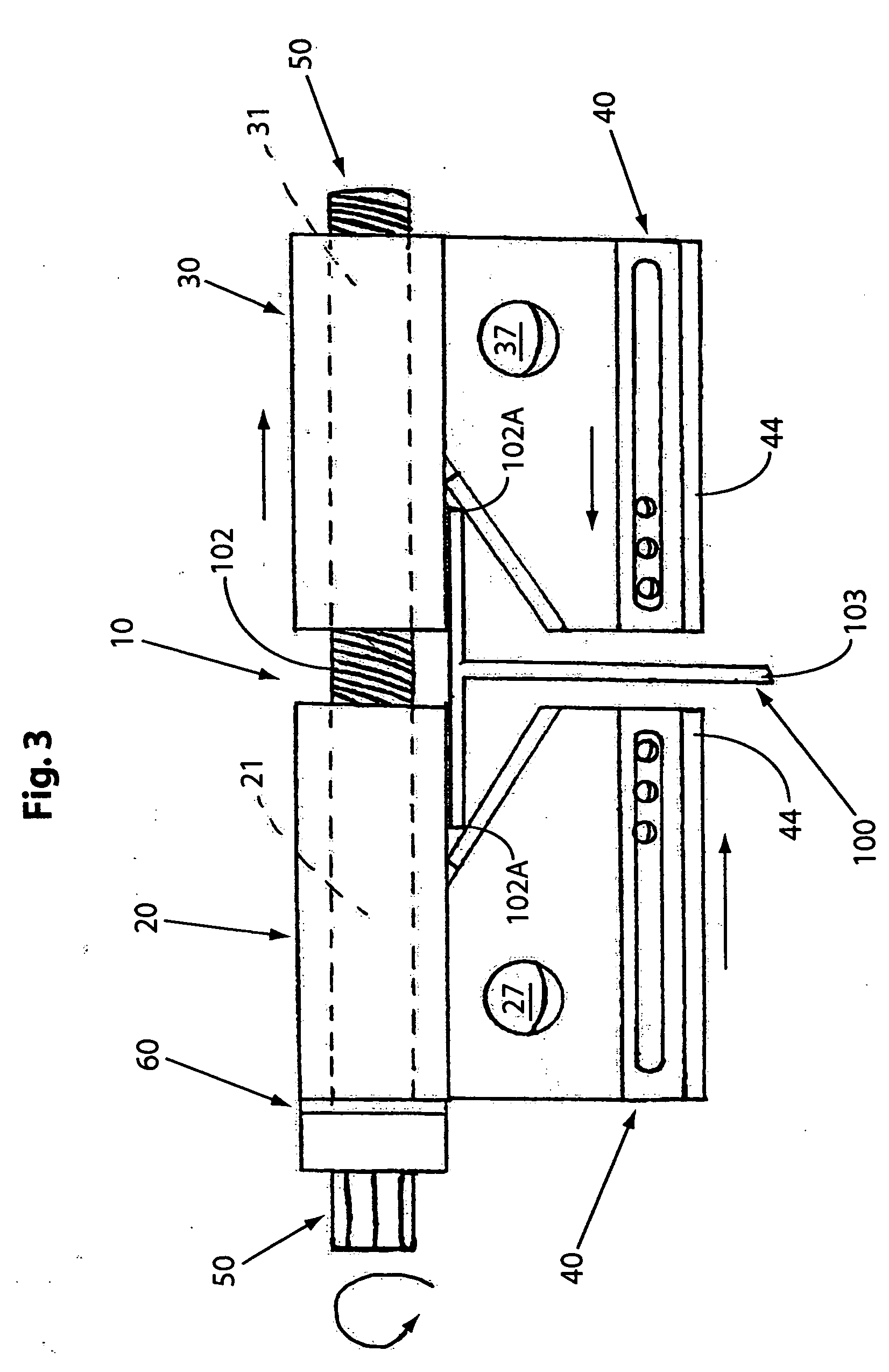
[0063] Referring now to the drawing, and in particular to FIGS. 3-8, the exemplary, 1st embodiment of the over-all clamp system of the present invention is designated generally by the numeral 10 and is made of the following basic parts: [0064] a first, side-gripping or engaging, clamping element 20 having a smooth, longitudinally extended, end-to-end bore 21 (FIGS. 4A &4B); [0065] a second, side-gripping or engaging, clamping element 30 having a threaded, longitudinally extended, end-to-end bore 31 (FIGS. 5A &5B); [0066] two, supplemental, lower, supporting or anchoring elements 40 (FIGS. 6A & 6B), one for the bottom or lower end 22 of side gripping element 20 and the other for the lower end 32 of the other, side gripping element 30; and [0067] a threaded, driving rod element 50 (FIG. 7), which in use will be inserted through the smooth bore of the first clamp element and an associated washer element 60 (FIG. 8), ...


PUM


Abstract

A clamping system (10/110) for holding, supporting or lifting a heavy work piece (200; e.g. a pipe section of pipe line of hundreds of pounds) located below a girder (100) using rigging (210) attached to the clamp at attachment openings (27/37, 127/137) equally spaced from the center-line web (103) of the girder, which clamping system is attached to opposed, side edges of the top flange member (102) of the girder (vis-a-vis the bottom flange member 101), or in a second embodiment (FIGS. 9+) to either the top or the bottom. In the second embodiment a straight bar (150) with a series of spaced, locking cavities (151a/b) is used in place of the threaded rod, threaded engagement of the first embodiment, with the cavities working with spring-biased pin latches on the side gripping elements. When used on the bottom flange, a slidable, load supporting, centrally located accessory (160) is used.

Description

REFERENCE TO RELATED APPLICATION [0001] This application is a substitute application of previously pending patent application Ser. No. 10 / 404,177 filed Mar. 31, 2003, which in turn was a substitute application of Ser. No. 09 / 675,964 filed Sep. 29, 2000 of the same title hereof, which in turn was a continuation-in-part application of then pending patent application Ser. No. 09 / 435,139, filed Nov. 5, 1999 entitled “Top-Mount, Heavy Load Bearing, Girder Clamp System,” the disclosures of which are incorpo-rated herein by reference. It is noted that FIGS. 1-8 hereof and the relevant written description below are taken from the first filed application, while FIGS. 9+ and the relevant written description are added in the second filed, continuation-in-part application, which is substantively identical to the instant application. No claim under 35 USC 120 is made based on any of these application and no co-pendency exists. These prior filings are relevant to showing earlier dates of construc...

Claims


Application Information

Patent Timeline
IPC IPC(8): G09F7/18
CPCG09F7/18G09F2007/186
Inventor GULLEY, WILLIAM F.
Owner GULLEY WILLIAM F
Why Eureka
Try Eureka