
Display device

Inactive Publication Date: 2007-04-26
ORION ELECTRIC CO LTD
View PDF4 Cites 4 Cited by
  • Summary
  • Abstract
  • Description
  • Claims
  • Application Information

AI Technical Summary

Benefits of technology

[0007] The present invention is implemented in view of the above described problems and it is an object of the present invention to provide a display device capable of changing the inclination of a display section according to the user's preferences and stably keeping the angle of the display section.
[0016] According to the display device of a first aspect of the present invention, it is possible to easily change the mounting angle of the display section with respect to the stand section according to the angle of the fixed section and extremely stably support the legs by directly fixing the legs to the fixed plate without the angle of the display plane being changed by the own weight of the display section.

Problems solved by technology

In this respect, in the liquid crystal display monitor described in Patent Document 2, it is possible to stably keep the mounting angle of the display section by supporting the display section using the locking means provided on the stand section, but the structure is complicated and the structure of supporting the large screen display section using the locking means as described above causes the weight of the display section to be locally concentrated, which makes it difficult for the locking means to support the heavy display section, leaving a problem that it is difficult to stably support the display section.

Method used


Image

  • Display device
  • Display device
  • Display device

Examples


embodiment 1

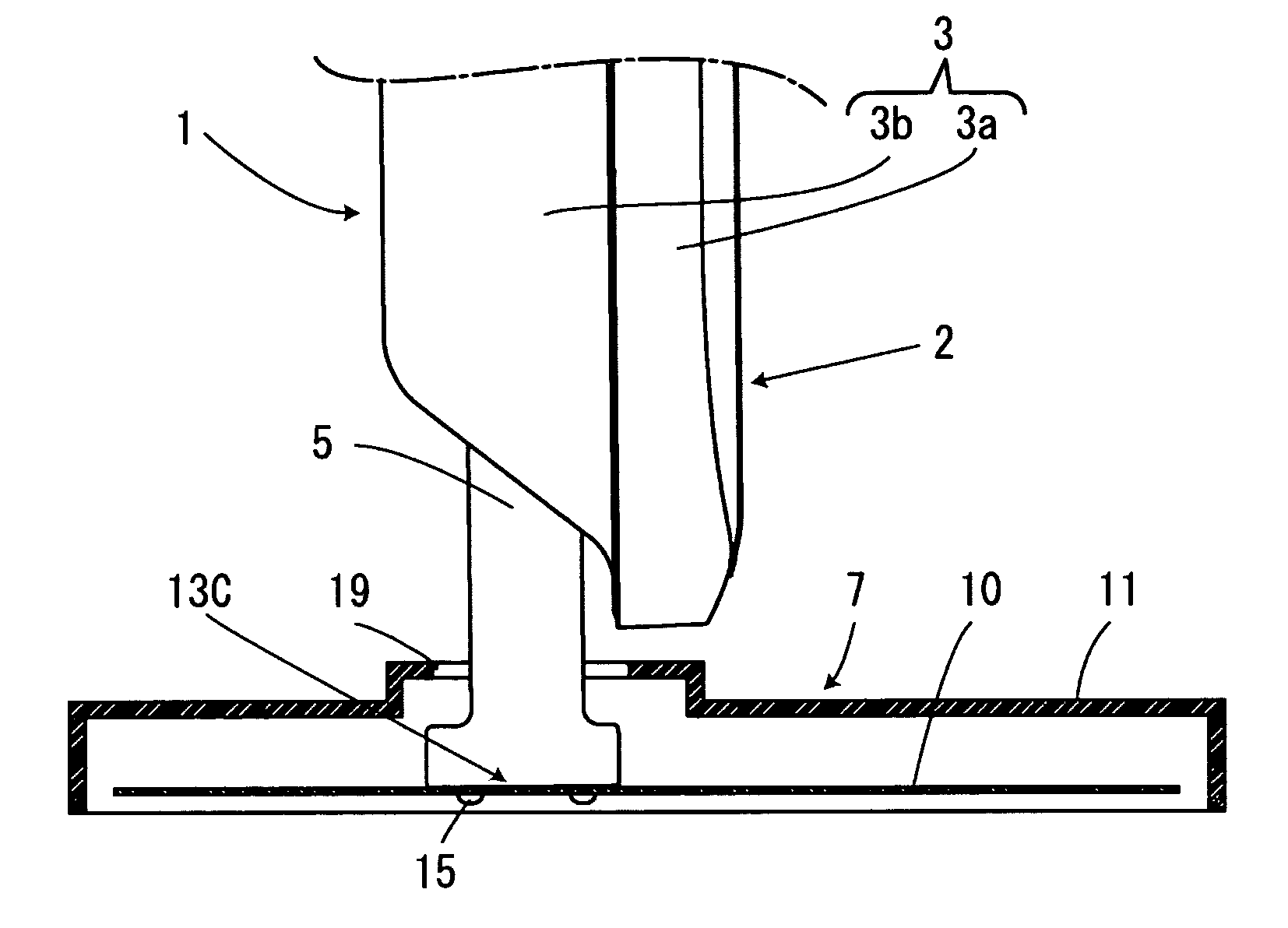
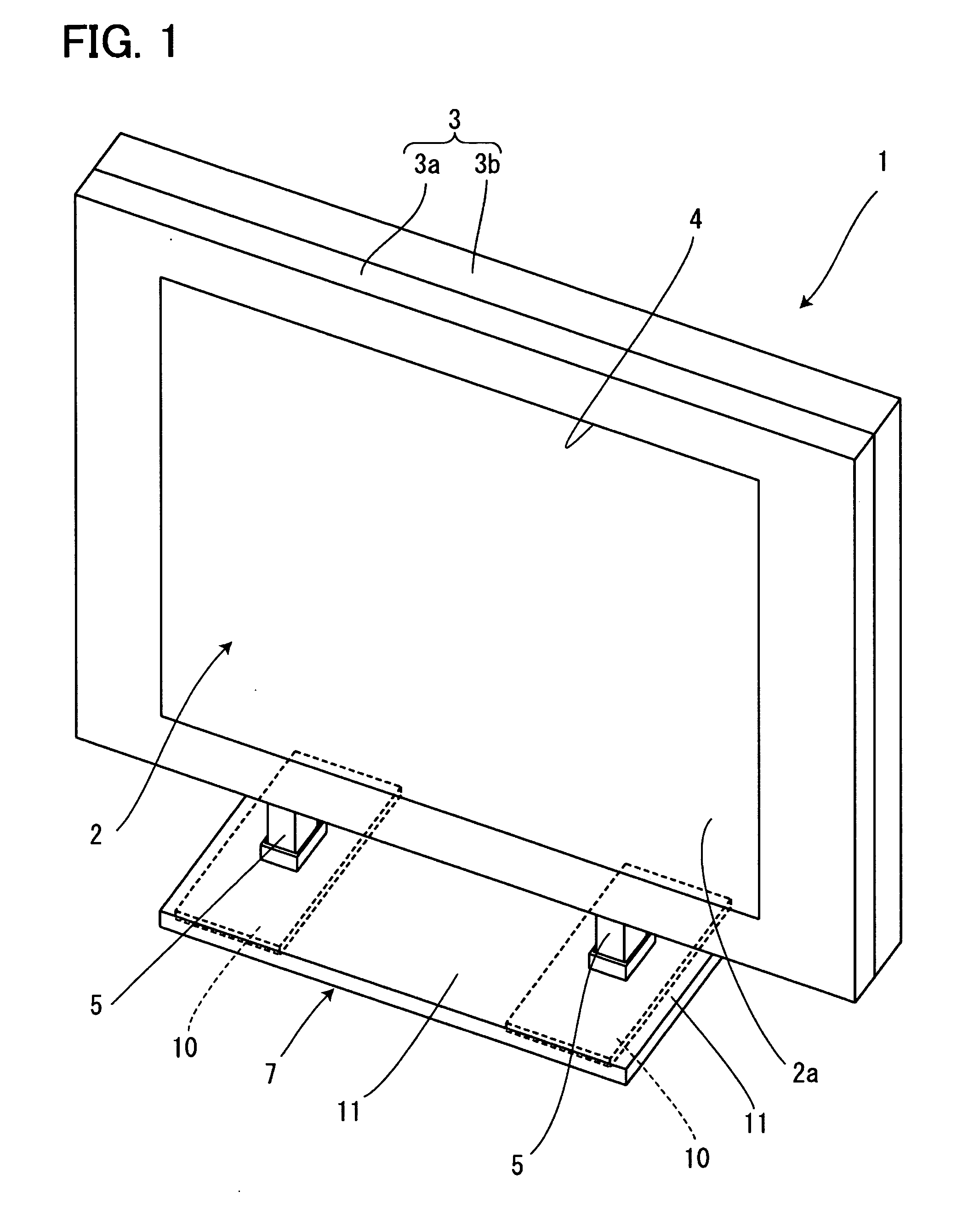
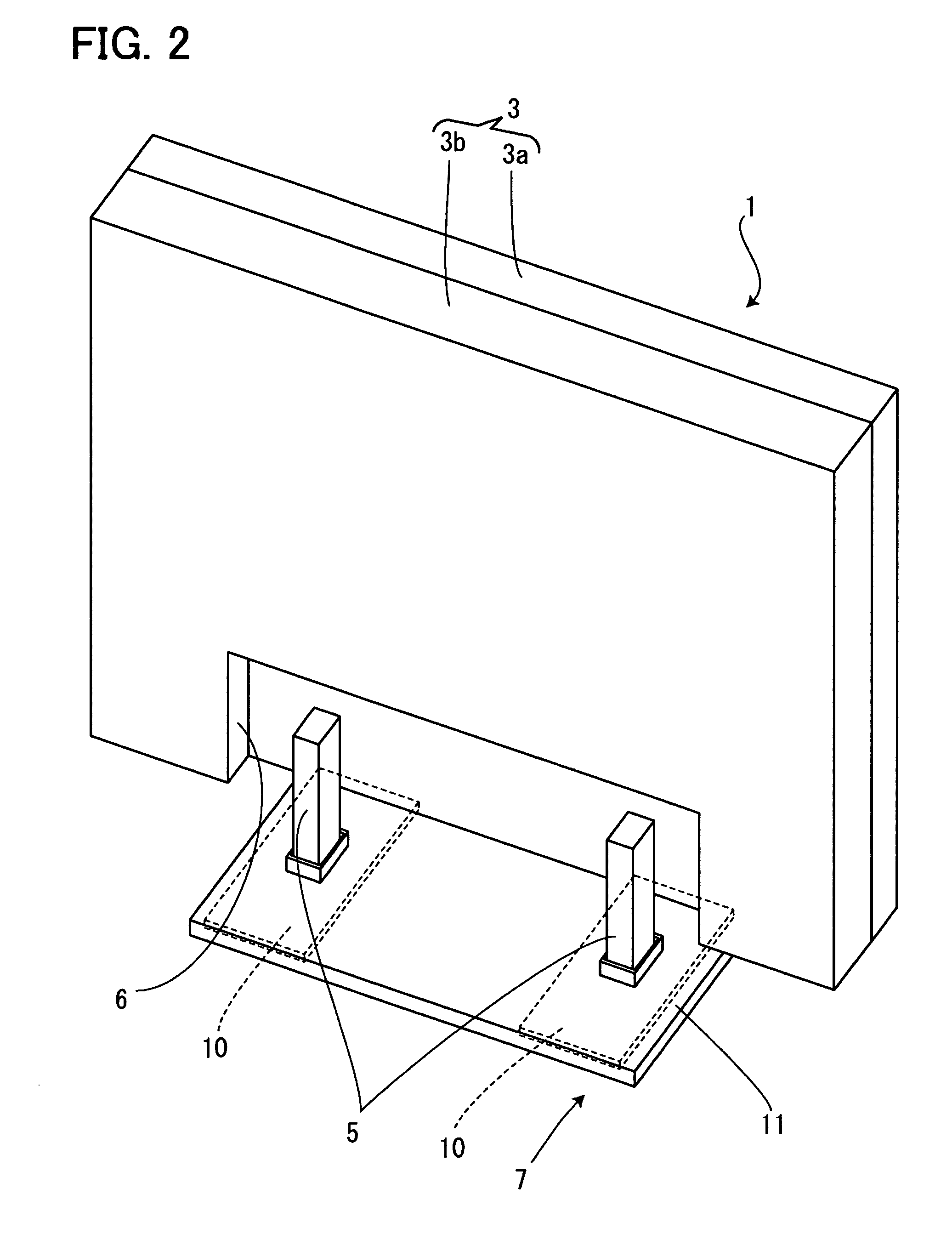
[0031]FIG. 1 to FIG. 6 show Embodiment 1 of the present invention; FIG. 1 is a perspective view of a display device viewed from the front, FIG. 2 is a perspective view of the display device viewed from the back, FIG. 3 is a perspective view of the fixed plate, FIG. 4 is a cross sectional view showing the display section before being mounted, FIG. 5 to FIG. 7 show the display section with its mounting angle changed; FIG. 5 shows a case where the display section is mounted in an upright position, FIG. 6 shows a case where the display section is inclined backward and FIG. 7 shows a case where the display section is inclined forward. In the figures, reference numeral 1 denotes a display section, which is constructed of a liquid crystal panel 2 and a cabinet 3 which houses this liquid crystal panel 2. The cabinet 3 is divided into front and rear portions; a front cabinet 3a and a rear cabinet 3b, the front cabinet 3a is provided with a display window 4 which exposes a display plane 2a of...

first embodiment

[0038] As shown above, in this embodiment, the horizontal substrate 21, inclined substrates 22A, 22B to be fixed to the fixed plate 10 in a freely detachable manner are formed and any one of the horizontal substrate 21, inclined substrates 22A, 22B is fixed to the fixed plate 10, and it is thereby possible, as in the case of the first embodiment, to cause the horizontal substrate 21 or inclined substrates 22A, 22B selectively mounted on the fixed plate 10 to change the mounting angle of the display section 1.

third embodiment

[0039]FIG. 9 shows perspective views of a fixed plate according to the present invention and parts having the same functions as those in the foregoing embodiments are assigned the same reference numerals, explanations of overlapping parts will be omitted and only different parts will be explained.


PUM


Abstract

To make it possible to change a mounting angle of a display section with respect to a stand section and reliably keep the angle of the display section without being changed with the own weight. A fixed section 13A made up of an inclined plane 14A inclined backward, a fixed section 13B made up of an inclined plane 14B inclined forward and a horizontal fixed section 13C located on the same plane as that of a fixed plate 10 are formed in the fixed plate 10 which is to be fixed to a stand section 7 for supporting a display section 1. A mounting angle of the display section 1 is changed with respect to the stand section 7 by selectively fixing legs 5 to any one of these fixed sections 13A to 13C.

Description

[0001] The present application is based on and claims priority of Japanese patent application No. 2005-305202 filed on Oct. 20, 2005, the entire contents of which are hereby incorporated by reference. BACKGROUND OF THE INVENTION [0002] 1. Field of the Invention [0003] The present invention relates to a display device provided with a display section having a display surface such as a liquid crystal panel and a stand section which supports this display section, and more particularly, to a display device which can change an angle of mounting the display section on the stand section. [0004] 2. Description of the Related Art [0005] A display device using a thin flat panel such as PDP (Plasma Display Panel), for example, a liquid crystal panel is becoming widespread as a display device for a television receiver or personal computer in recent years. Such a display device using a liquid crystal panel is provided with a stand for supporting the display section. Various types of structures ar...

Claims


Application Information

Patent Timeline
IPC IPC(8): G06F1/16
CPCF16M11/00F16M11/10F16M11/22F16M2200/08
Inventor UCHIZONO, TATSUYATAJIMA, KOICHI
Owner ORION ELECTRIC CO LTD
Learn More