
Pump and valve actuator system and method

a valve actuator and valve actuator technology, applied in the direction of pump components, positive displacement liquid engines, liquid fuel engine components, etc., can solve the problems of high manufacturing costs and limited market availability of this pump styl

Inactive Publication Date: 2007-04-26
SHURFLO
View PDF37 Cites 43 Cited by
  • Summary
  • Abstract
  • Description
  • Claims
  • Application Information

AI Technical Summary

Benefits of technology

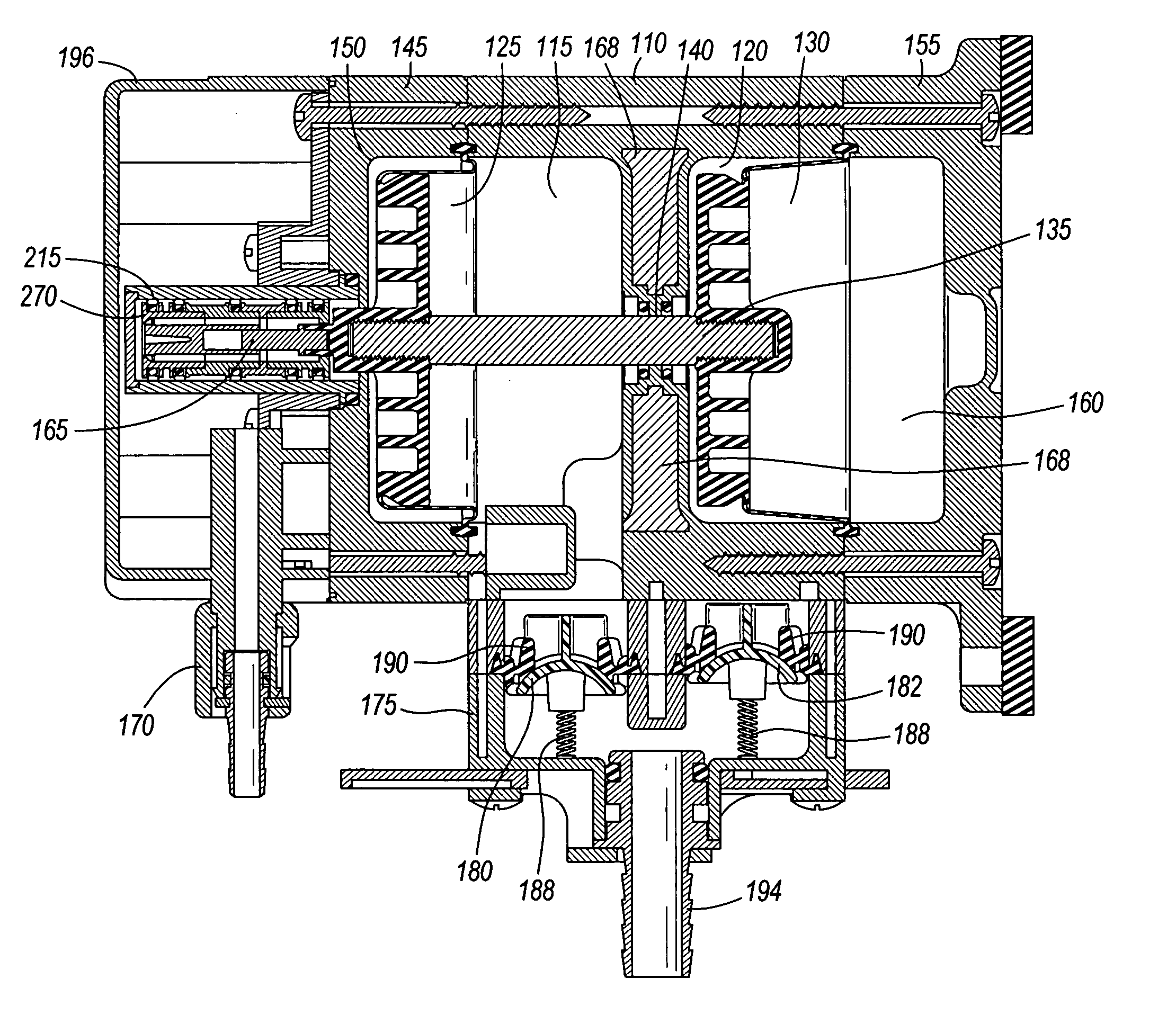
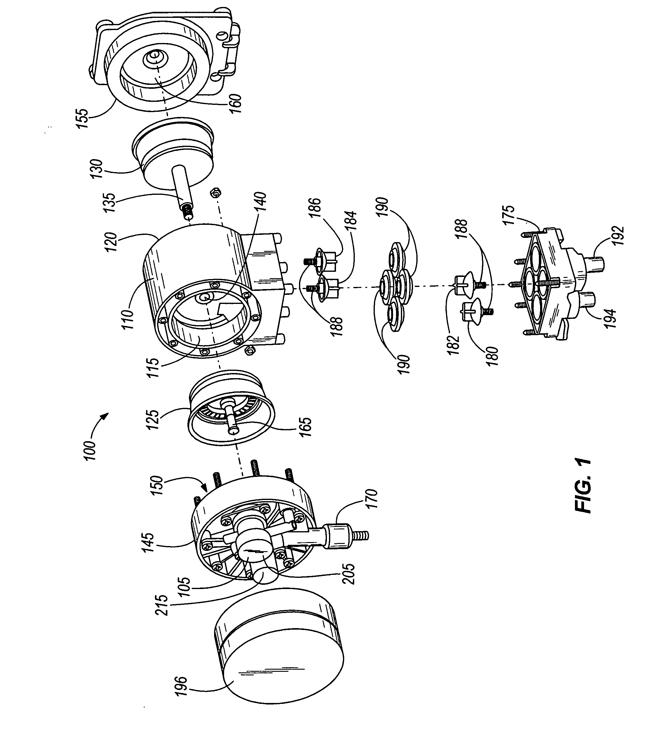
[0005] Embodiments of the invention provide an actuator assembly with a housing which can include a first chamber and a second chamber. A pilot spool valve can be positioned in the first chamber and a main spool valve can be positioned in the second chamber. Between the first and second chambers can be a first lens-shaped port an

Problems solved by technology

This has resulted in high manufacturing costs and limited the markets available to this style of pump.

Method used


Image

  • Pump and valve actuator system and method
  • Pump and valve actuator system and method
  • Pump and valve actuator system and method

Examples


Embodiment Construction

[0033] Before any embodiments of the invention are explained in detail, it is to be understood that the invention is not limited in its application to the details of construction and the arrangement of components set forth in the following description or illustrated in the following drawings. The invention is capable of other embodiments and of being practiced or of being carried out in various ways. Also, it is to be understood that the phraseology and terminology used herein is for the purpose of description and should not be regarded as limiting. The use of “including,”“comprising,” or “having” and variations thereof herein is meant to encompass the items listed thereafter and equivalents thereof as well as additional items. Unless specified or limited otherwise, the terms “mounted,”“connected,”“supported,” and “coupled” and variations thereof are used broadly and encompass both direct and indirect mountings, connections, supports, and couplings. Further, “connected” and “couple”...


PUM


Abstract

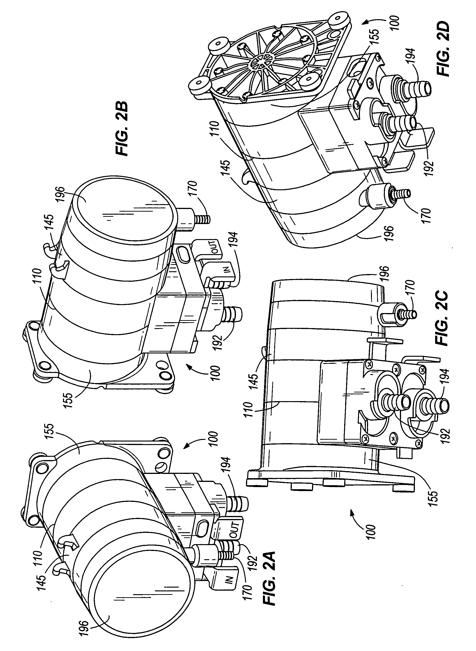
A double diaphragm pump including a dual spool valve actuator. A set of piston / diaphragm assemblies can be coupled to a pilot spool valve, which can direct air flow to a main spool valve. The main spool valve can direct air flow to pump chambers. Components of the pump can be manufactured by injection molding and press-fit together. The pump can include lens-shaped ports and positive-return poppet valves.

Description

FIELD OF THE INVENTION [0001] The invention generally relates to reciprocating pumps, such as compressed air-operated, double-diaphragm pumps, having a main spool valve and a pilot spool valve. BACKGROUND OF THE INVENTION [0002] Air-driven diaphragm pumps generally include two opposed pumping cavities. The pumping cavities each include a pump chamber, an air chamber, and a diaphragm extending fully across the pumping cavity defined by these two housings. Each pump chamber includes an inlet check valve and an outlet check valve. A common shaft typically extends into each air chamber to attach to the diaphragms. [0003] An actuator valve receives a supply of pressurized air and operates through a feedback control system to alternately pressurize and vent the air chamber side of each pumping cavity through a spool valve piston. Feedback to the pilot spool valve has been provided by the position of the shaft attached to the diaphragms, which includes one or more passages to alternately v...

Claims


Application Information

Patent Timeline
IPC IPC(8): F04B43/06
CPCF04B43/0736F04B53/102F04B53/22
Inventor PETRIE PE, GREG A.
Owner SHURFLO
Learn More