
Molding apparatus for optical elements

a technology of optical elements and molding apparatus, which is applied in the direction of glass pressing apparatus, turning machine accessories, drawing profiling tools, etc., can solve the problems of difficult to separate the duly formed lens from the lower molding surface, and the manufacturing of lenses using conventional polishing methods is problemati

Inactive Publication Date: 2007-04-26
HON HAI PRECISION IND CO LTD
View PDF36 Cites 26 Cited by
  • Summary
  • Abstract
  • Description
  • Claims
  • Application Information

AI Technical Summary

Benefits of technology

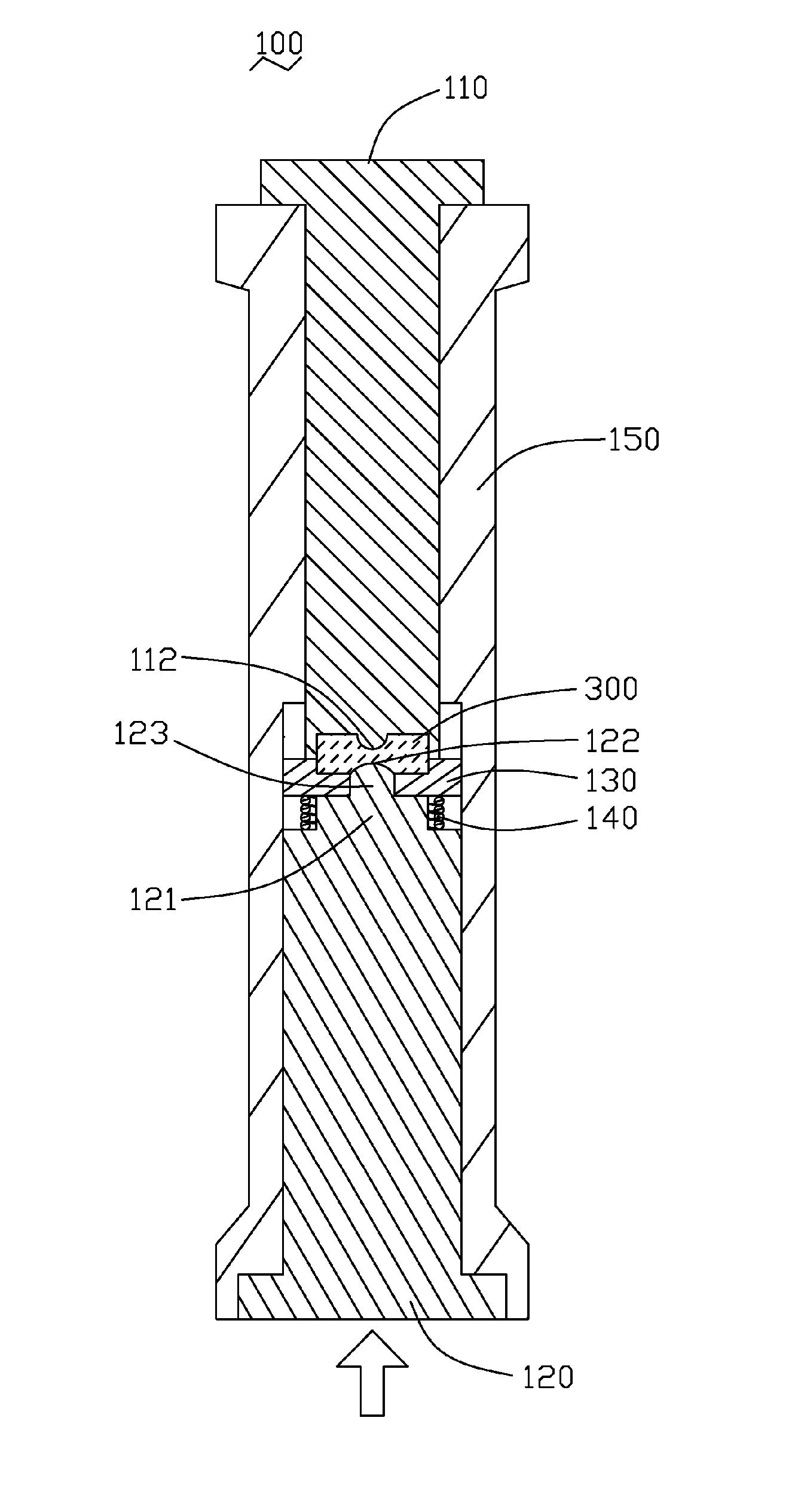
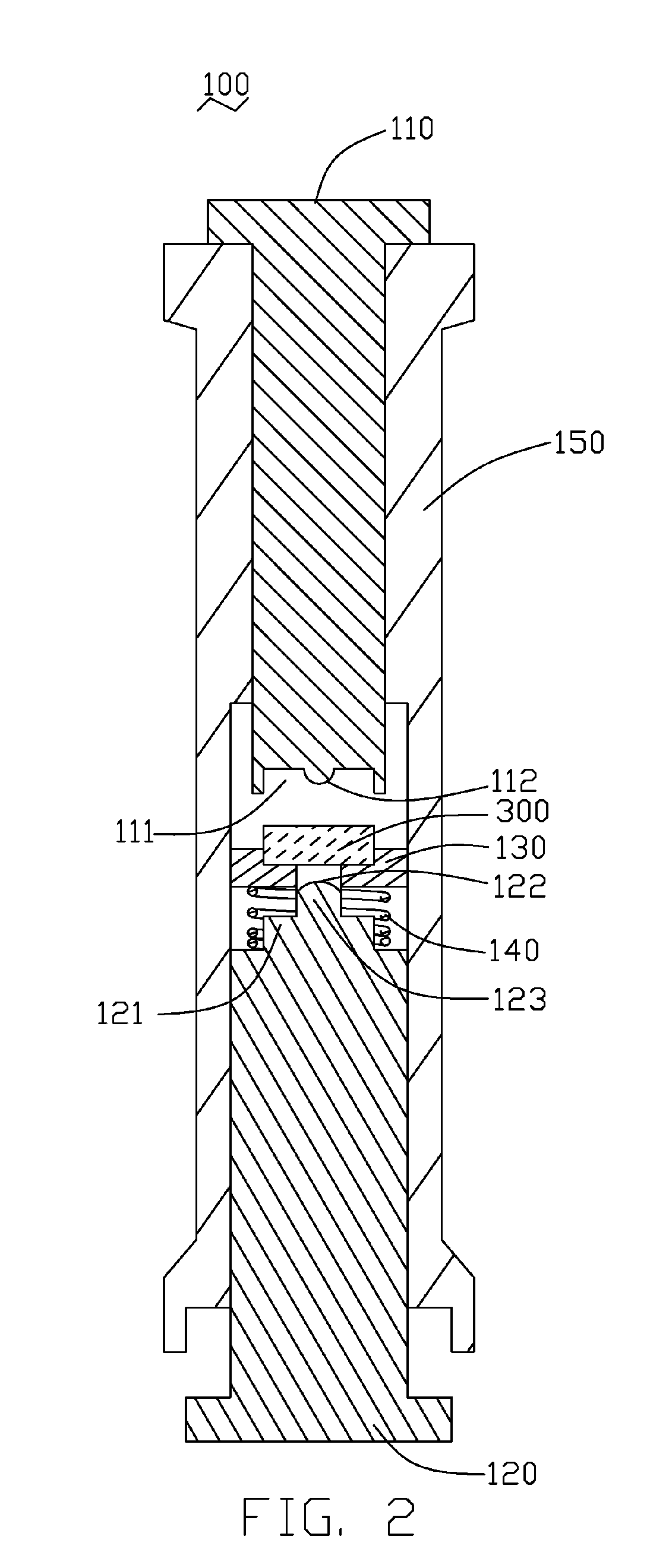
[0007] A molding apparatus for press molding optical elements is provided. In one embodiment, the molding apparatus includes a first mold core, a second mold core, a lens holder, an elastic member, and a mold frame. The first mold core is substantially cylindrical, and defines a convex first molding surface for press molding a top surface of a lens preform. The second mold core is substantially cylindrical, and defines a convex second molding surface for press molding a bottom surface of the lens preform. The lens holder defines a cavity in a center of a top portion thereof, for fitting the lens preform therein during molding. The lens holder further defines a central through hole, for allowing the second molding surface to pass up therethrough and press the bottom surface of the lens preform.

Problems solved by technology

However, the manufacturing of lenses using conventional polishing methods is problematic.
Then it is difficult to separate the duly formed lens from the lower molding surface 221.

Method used


Image

  • Molding apparatus for optical elements
  • Molding apparatus for optical elements
  • Molding apparatus for optical elements

Examples


Embodiment Construction

[0016] Reference will now be made to the drawings to describe embodiments of the present molding apparatus in detail.

[0017] Referring to FIG. 1, a molding apparatus 100 for press molding optical elements according to a preferred embodiment of the present invention is shown. The molding apparatus 100 includes a first mold core 110, a second mold core 120, a lens holder 130, an elastic member 140, and a mold frame 150. Also referring to FIG. 2, the first mold core 110 is substantially cylindrical. The first mold core 110 defines a concavity 111 at a bottom end thereof, for receiving a lens preform 300 therein. The first mold core 110 has a convex first molding surface 112 in the concavity 111, for press molding a top surface of the lens preform 300. The first mold core 110 is movably positioned in the mold frame 150.

[0018] The second mold core 120 is substantially cylindrical. The second mold core 120 includes a stamp 121 at a top end thereof. A protrusion portion 123 protrudes up f...


PUM

PropertyMeasurementUnit
Moldableaaaaaaaaaa
Elasticityaaaaaaaaaa

Abstract

An exemplary molding apparatus (100) includes a first mold core (110), a second mold core (120), a lens holder (130), an elastic member (140) and a mold frame (150). The first mold core is substantially cylindrical and has a first molding surface for press molding a top surface of a lens. The second mold core is substantially cylindrical and has a second molding surface for press molding a bottom surface of the lens. The lens holder has a cavity for fitting the lens. The elastic member is a spring. The elastic member is placed between the lens holder and the second mold core. The first mold core, the second mold core, the lens holder and the elastic member are disposed in the mold frame.

Description

FIELD OF THE INVENTION [0001] The invention relates generally to molding apparatuses, and more particularly to a molding apparatus for press molding optical elements such as lenses. DESCRIPTION OF RELATED ART [0002] In recent times there has been a trend for electrical products, such as digital cameras and mobile phones with digital camera modules, to be compact, lightweight and inexpensive. To meet this demand, a number of simplified lens systems have been developed. However, the manufacturing of lenses using conventional polishing methods is problematic. For this reason, manufacturing lenses by a press molding method has become popular. [0003] A conventional press molding method for making a glass lens involves molding a piece of glass material using a molding apparatus. The molding apparatus generally includes an upper mold core, a lower mold core, and a mold frame for slidably holding the upper and lower mold cores therein. Referring to FIG. 4, a typical molding apparatus 200 in...

Claims


Application Information

Patent Timeline
IPC IPC(8): B29C33/00
CPCB29C43/021B29C43/361B29C2043/3255B29C2043/3618B29C2043/3652B29C2043/5841B29D11/00413B29L2011/0016C03B11/08C03B2215/06C03B2215/49C03B2215/61C03B2215/72
Inventor CHIANG, TSUNG-WEI
Owner HON HAI PRECISION IND CO LTD
Learn More