System and method for onboard vision processing

a vision processing and system technology, applied in the field of unmanned aerial vehicles, can solve the problems of not being able to make the transition to a fully autonomous state, not being able to fly in the presence of obstacles, and limited current uavs, so as to increase the capability of vision-based estimation

Inactive Publication Date: 2007-04-26
PRIORIA ROBOTICS
View PDF9 Cites 234 Cited by
  • Summary
  • Abstract
  • Description
  • Claims
  • Application Information

AI Technical Summary

Benefits of technology

[0013] The present invention provides a motion-compensated onboard vision processing system that combines inputs from at least one vision sensor and at least one motion sensor to increase the capabilities of vision-based estimation for the purpose of navigation and stabilization, and thus provides a system capable of exploring unknown environments, surviving in cluttered environments, or adapting to dynamic, obstacle-rich environments.

Problems solved by technology

Current UAVs are limited in that, while capable of basic semi-autonomous operation, they have not yet been able to make the transition to a fully autonomous state.
The principal source of this limitation is the fact that, while they can generally maneuver in an open-air environment by remote control or simple waypoint navigation, they cannot fly in the presence of obstacles such as buildings, trees, or towers, because their navigation systems are based on position alone.
Problems arise when obstacles are present between waypoint markers.
It does not, however, free the aircraft to safely explore areas where the terrain is dynamic, where obstacles are largely unmapped, or where the environment is physically cluttered (the streets of a city or town, for example).
However, radar-type systems require payload and power capabilities orders of magnitude larger than what UAVs can support.
These systems also emit large levels of detectable energy during their operation.
This system provides no means to navigate in an unknown or dynamic environment or to adapt to the presence of multiple obstacles.
The reconstructions (or estimations) obtained from the feature correspondences between frames are subject to a high-degree of projective ambiguity.
When compared with a native three-dimensional radar-type imaging system output, the three-dimension computer vision scene estimates, and camera motions, are low-resolution and very prone to instantaneous noise (large variations between frames).
This system provides a method for determining the presence of an obstacle using a three-dimensional analysis approach, but would fall short in an unknown or dynamic environment, or where multiple obstacles are present, because it relies on a priori knowledge (offline training) that would not be available in those cases.

Method used


Image

  • System and method for onboard vision processing
  • System and method for onboard vision processing
  • System and method for onboard vision processing

Examples


Embodiment Construction

[0031] This invention is not limited in its application to the details of construction and the arrangement of components set forth in the following description or illustrated in the drawings. The invention is capable of other embodiments and of being practiced or of being carried out in various ways. Also, the phraseology and terminology used herein is for the purpose of description and should not be regarded as limiting. The use of “including,”“comprising,” or “having,”“containing,”“involving,” and variations thereof herein, is meant to encompass the items listed thereafter, and equivalents, as well as additional items.

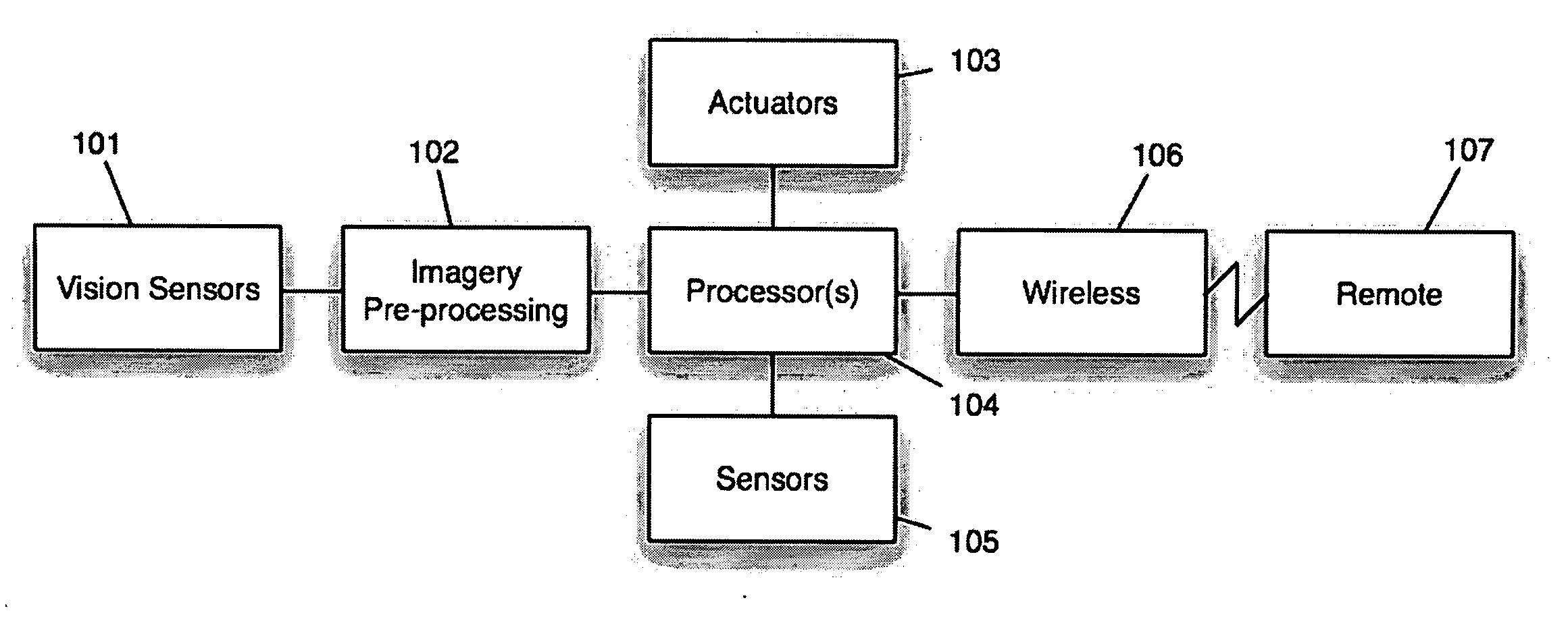
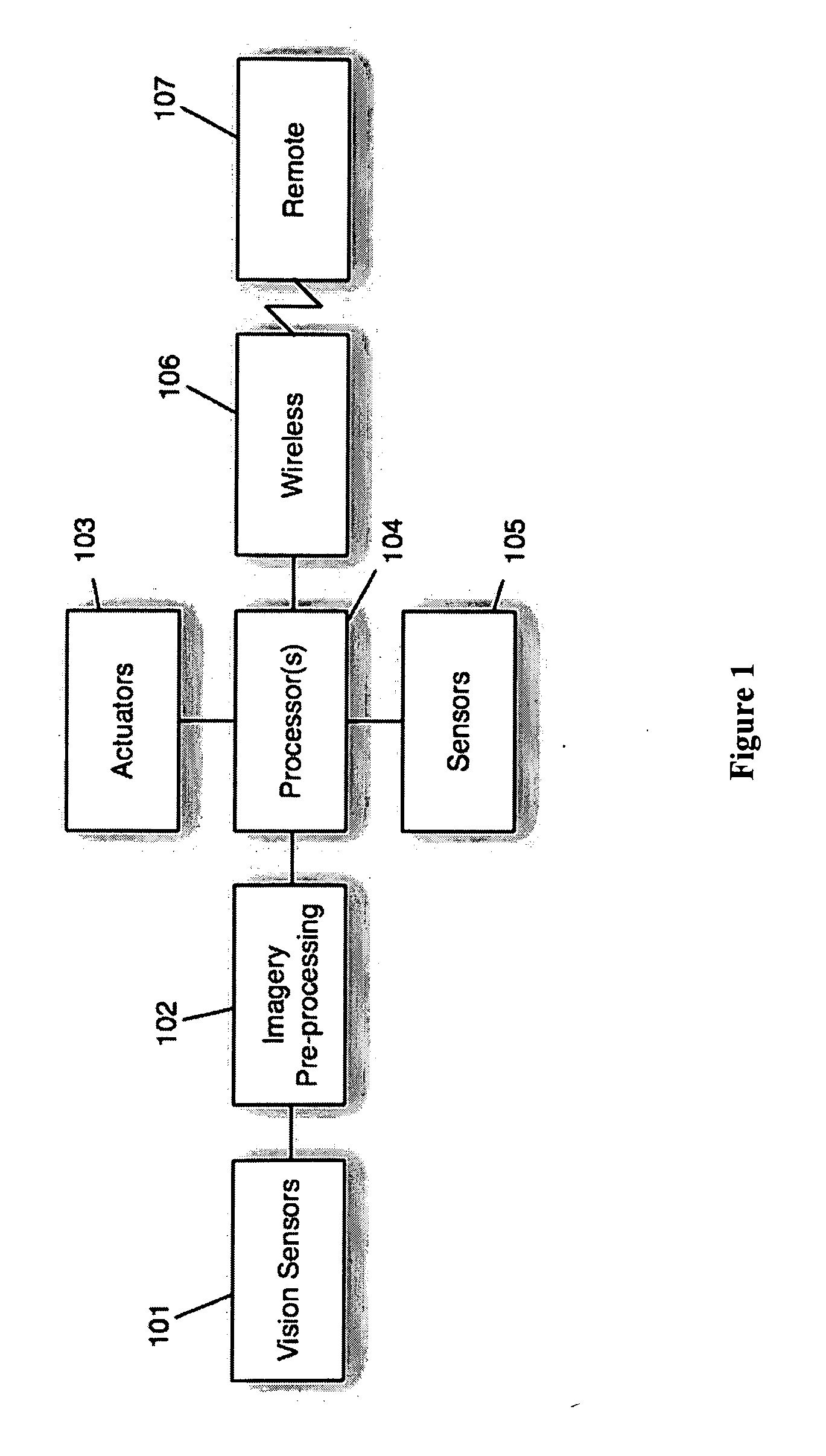
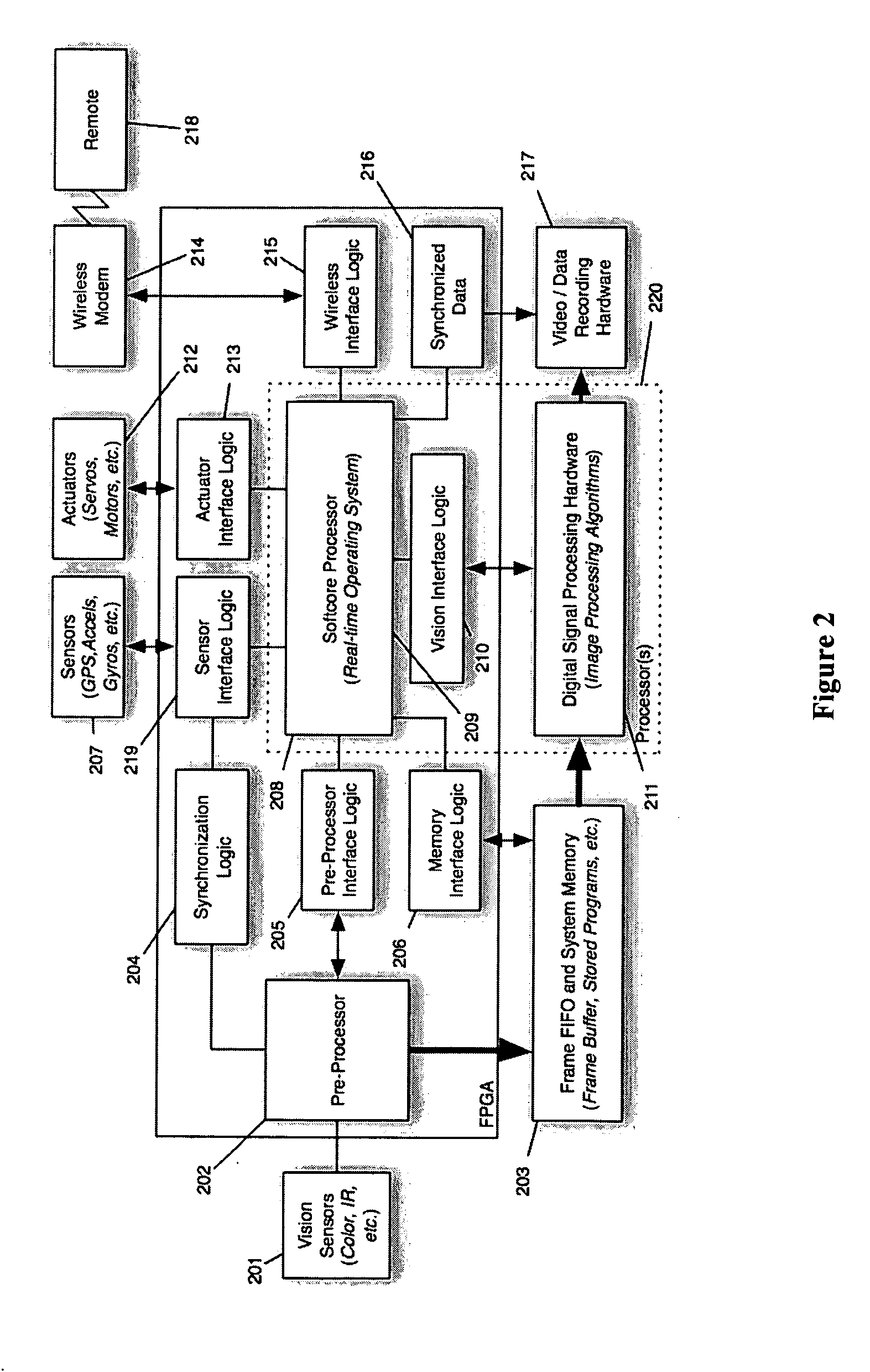
[0032] As described above, the current use of vision in UAVs to navigate is problematic in all but a few isolated, ideal cases and. A system that improves upon what can be estimated by vision alone is needed. Motion sensors (e.g., accelerometers, gyroscopes, and GPS) are present on modem UAVs and are used to support position-based navigation. While such sensors are ...


PUM


Abstract

An unmanned aerial vehicle with a camera and conventional sensors, where the processor navigates the vehicle based at least in part on the image data and the sensor data. A method for navigating an unmanned aerial vehicle where a processor navigates the vehicle based at least in part on image data corrected by traditional sensor data.

Description

RELATED APPLICATIONS [0001] This application claims priority under 35 U.S.C. § 119(e) to U.S. Provisional Application Ser. No. 60 / 728,708, entitled “System And Method For Onboard Vision Processing,” filed on Oct. 20, 2005, which is herein incorporated by reference in its entirety.BACKGROUND [0002] This invention generally concerns unmanned aerial vehicles (“UAVs”), such as planes, helicopters, balloons, and the like, that are operated without need of a person being onboard. [0003] Current large-scale UAVs, defined to be those with wingspans greater than twenty feet (e.g., the Predator and the Global Hawk) have been developed to fulfill tactical combat support roles, such as high-altitude surveillance and munitions delivery, while keeping the human pilot out of harm's way. These planes were designed to be similar in function to their on-board, human-piloted counterparts, typically having payloads of several hundred pounds, running on fuel-powered engines, and being capable of flying ...

Claims


Application Information

Patent Timeline
Patent Type & Authority Applications(United States)
IPC IPC(8): G01C22/00
CPCG01C21/005G05D1/101G05D1/106
Inventor GRZYWNA, JASON W.DA FROTA, BRYANMEUSE, STEPHEN
Owner PRIORIA ROBOTICS
Why Eureka
Try Eureka