

Executable and declarative specification for graphical user interfaces
a graphical user interface and declarative technology, applied in the field of graphical user interfaces, can solve problems such as difficulty in affecting the evolution of model representations
- Summary
- Abstract
- Description
- Claims
- Application Information
AI Technical Summary
Problems solved by technology
Method used
Image

Examples
example # 1
Example #1
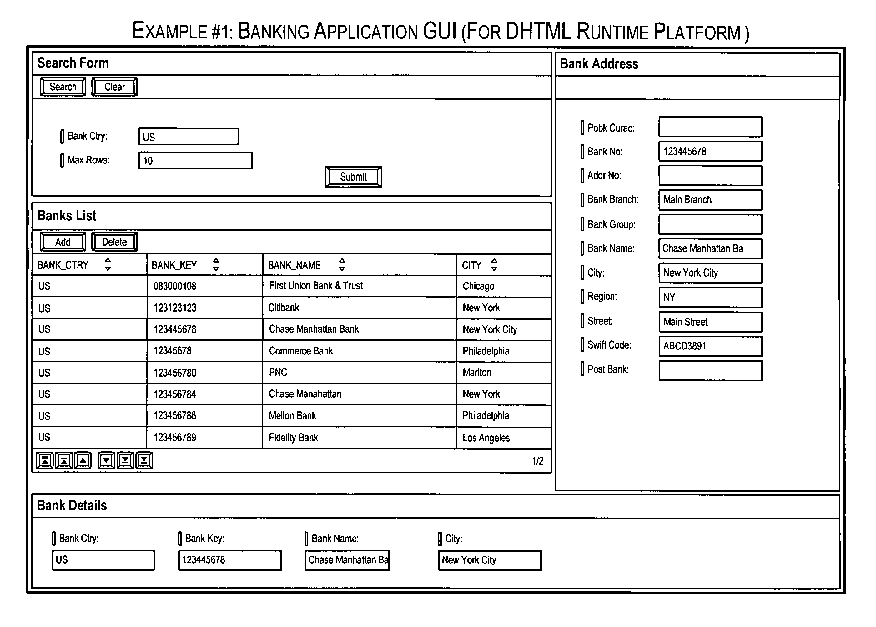
[0058] In this example, a GUI is developed for a bank data entry application. The overall processing flow applicable to example #1 is depicted in FIG. 4A. A design-time model representation 402 is provided encapsulating the GUI for the application. A visual representation of the model representation for the bank data-entry application GUI is depicted in FIG. 4B. As depicted in FIG. 4B, the GUI comprises several components with connections between the components. Inputs and output for the GUI components are also shown.
[0059] An XGL generator 404 is used to generate an XGL representation 406 for the model representation. XGL generator 404 may use mapping rules to transform the model representation to an XGL representation. According to an embodiment of the present invention, the XGL representation may be in the form of an XML file. An XGL representation in XML for the model representation depicted in FIG. 4B is provided in Appendix A of U.S. Provisional Patent Application N...
example # 2
Example #2
[0064] In this example, a GUI is developed for an analytics dashboard. The overall processing flow applicable to example #2 is depicted in FIG. 5A. A design-time model representation 502 is provided encapsulating the GUI for the application. A visual representation of the model representation for the analytics dashboard application GUI is depicted in FIG. 5B. As depicted in FIG. 5B, the GUI comprises several components with connections between the components. Inputs and output for the GUI components are also shown.
[0065] An XGL generator 504 is used to generate an XGL representation 506 for the model representation. XGL generator 404 may use mapping rules to transform the model representation to an XGL representation. According to an embodiment of the present invention, the XGL representation may be in the form of an XML file. An XGL representation in XML form for the model representation depicted in FIG. 5B is provided in Appendix D of U.S. Provisional Patent Application...
example embodiment
A Sample XGL Specification (Example Embodiment)
[0069] This section describes a specific embodiment of an XGL specification. The sample embodiment described in this section is however not intended to limit or narrow the scope of the present invention as recited in the claims. Various others types of XGL specifications that are declarative and executable may also be provided in accordance with the present invention.
[0070] Details related to the XGL specification embodiment described in this section are provided in Appendix G of U.S. Provisional Patent Application No. 60 / 722,888 (Attorney Docket No. 017900-005900US) filed Sep. 30, 2005, the entire contents (including all the appendices) of which are herein incorporated by reference for all purposes.
[0071] This section comprises the following sub-sections: [0072] 1. Document Structure
PART I: DATA MODEL [0073] 2. Fields and Expressions [0074] 3. Infosets [0075] 4. Infoactors [0076] 5. Operators [0077] 6. Enumerations
PART II: USER I...
PUM
 Abstract
Description
Claims
Application Information