Emergency alert signaling method and DTV receiver

a technology of emergency alert and signaling method, which is applied in the direction of television system, selective content distribution, instruments, etc., can solve the problems of inability to watch regular terrestrial broadcasts, inability to efficiently manage terrestrial broadcasts, and viewers located in an area with nothing

Inactive Publication Date: 2007-04-26
LG ELECTRONICS INC
View PDF2 Cites 37 Cited by
  • Summary
  • Abstract
  • Description
  • Claims
  • Application Information

AI Technical Summary

Benefits of technology

[0016] Another object of the present invention is to. provide a method of establishing an emergency alert channel in terrestrial broadcasting, data structure th thereof and broadcast receiver ...

Problems solved by technology

However, in operating the emergency alert system for the emergency in the terrestrial broadcasting, the related art has the following problems.
Hence, it is undesirable in aspect of the efficient management of the terrestrial broadcasting.
Secondly, as mentioned in the above description, if all channels of the terrestrial broadcasting simultaneously broadcast the almost similar newsflashes, viewers located in an area having nothing to do with the ...

Method used


Image

  • Emergency alert signaling method and DTV receiver
  • Emergency alert signaling method and DTV receiver
  • Emergency alert signaling method and DTV receiver

Examples


third embodiment

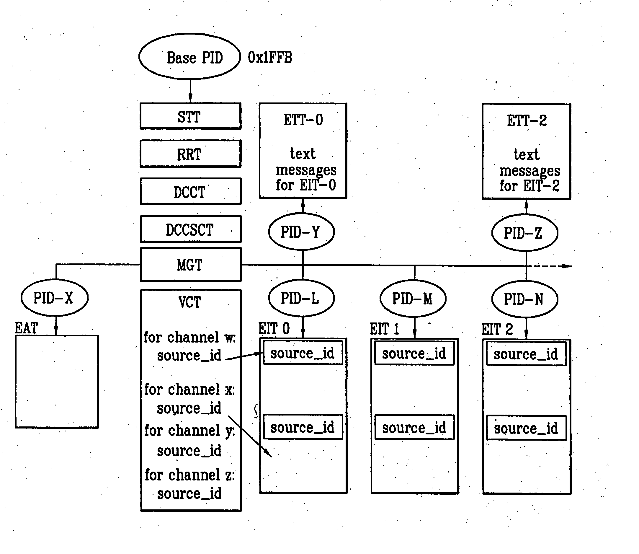
[0113] For the present invention, a portion of a reserved field in a bit stream syntax of MGT is used as an emergency flag. Yet, the emergency flag (emergency_flag) includes information notifying whether an emergency has taken place from a terrestrial broadcast transmitting side.

[0114] For instance, one bit, as shown in FIG. 7, is allocated to the emergency flag (emergency_flag). Of course, claims of the present invention are not limited to one-bit. If necessary, more bits can be allocated to the emergency flag (emergency_flag).

[0115] If the terrestrial broadcast transmitting side transmits an MGT by setting the emergency flag. (emergency_flag) to ‘0’, a terrestrial broadcast receiver side checks that the emergency flag (emergency_flag) of the received MGT is ‘0’and then confirms the emergency has taken place. Of course, the numerical value is just exemplary.

[0116] In this case, despite a channel that is being watched by a user, the terrestrial broadcast receiver side automaticall...

fourth embodiment

[0130] Yet, in the present invention, the emergency alert channel is defined more clearly. And, a method of registering the emergency alert channel to the terrestrial broadcast receiver and a process of tuning to the emergency alert channel according to a mode of the terrestrial broadcast receiver are explained in detail as follows.

[0131] First of all, the emergency alert channel means a channel of a specific broadband to transmit a broadcast having a content that indicates an occurrence, a variation status and the like of an emergency.

[0132] In defining the emergency alert channel, various methods are taken into consideration.

[0133] First of all, the emergency alert channel is designated using a new physical channel that is not assigned to conventional broadcasting stations.

[0134] Each conventional terrestrial broadcasting station uses a physical channel assigned by FCC (Federal Communications Commission). One of the physical channels except the channels assigned to the conventi...


PUM


Abstract

A terrestrial digital television receiver includes a tuner, a microcomputer, and a demodulator. The microcomputer initially determines whether the DTV receiver is on, a power-on or power-off mode. If the DTV receiver is on the power-off mode, the microcomputer, control operation of the tuner to tune to a predefined emergency alert channel to receive a master guide table. The demodulator parses the master guide table. If the parsed master guide table indicates that a new emergency alert message is being received, the microcomputer automatically sets the DTV receiver on the power-on mode and controls operation of the tuner to tune to the emergency alert channel.

Description

[0001] This application claims the benefit of Korean Patent Application No. 10-2005-0099649, filed on Oct. 21, 2005, which is hereby incorporated by reference. BACKGROUND OF THE INVENTION [0002] 1. Field of the Invention [0003] The present invention relates to an emergency alert system, and more particularly, to a method of establishing an emergency alert channel in terrestrial broadcasting, data structure thereof and broadcast receiver thereof. Although the present invention is suitable for a wide scope of applications, it is particularly suitable for newly defining a channel carrying information associated with an emergency and for providing information associated with an emergency to a user quickly and efficiently in the terrestrial broadcasting despite an environmental variation of a terrestrial broadcast receiver. [0004] 2. Discussion of the Related Art [0005] Recently, natural disasters including an unexpected earthquake, a flood and the like or emergency situations including ...

Claims


Application Information

Patent Timeline
IPC IPC(8): H04N7/10H04N5/44H04N5/00H04N5/445
CPCG08B27/008H04H20/59H04N5/4401H04N21/4345H04N21/4383H04N21/478H04N21/4882H04N21/814H04N21/8146H04H60/13H04N21/426H04N21/2668H04N21/462
Inventor KIM, JIN PILYUN, CHANG SIK
Owner LG ELECTRONICS INC
Why Eureka
Try Eureka