Needle Plate for Double-Needle Sewing Machine

Inactive Publication Date: 2007-05-03
SUSR MACHINERY
View PDF7 Cites 1 Cited by
  • Summary
  • Abstract
  • Description
  • Claims
  • Application Information

AI Technical Summary

Benefits of technology

[0008] Accordingly, the present invention has been made to solve these various problems occurring in the prior art, and an objective of the present invention is to provide a needle plate for a double-needle sewing machine, in which a partition and a thin plate inserted into the partition are provided between needle holes so as to reinforce the rigidity of a thin wall formed between needle holes, so that stitches can be formed in parallel without the needle plate being damaged even when the interval between the needle holes is less than 2 mm.

Problems solved by technology

Hence, it takes a great deal of expense and time to exchange the broken needle plate 10.

Method used


Image

  • Needle Plate for Double-Needle Sewing Machine
  • Needle Plate for Double-Needle Sewing Machine
  • Needle Plate for Double-Needle Sewing Machine

Examples


Embodiment Construction

[0019] Hereinafter, exemplary embodiments of the present invention will be described with reference to the accompanying drawings. In the following description and drawings, the same reference numerals are used to designate the same or similar components, and so repetition of the description on the same or similar components will be omitted.

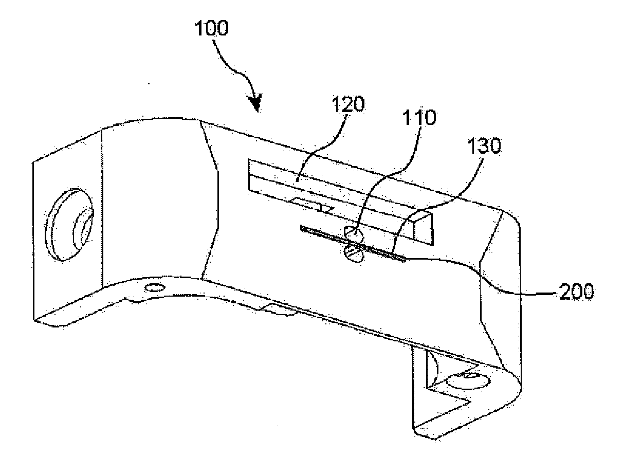
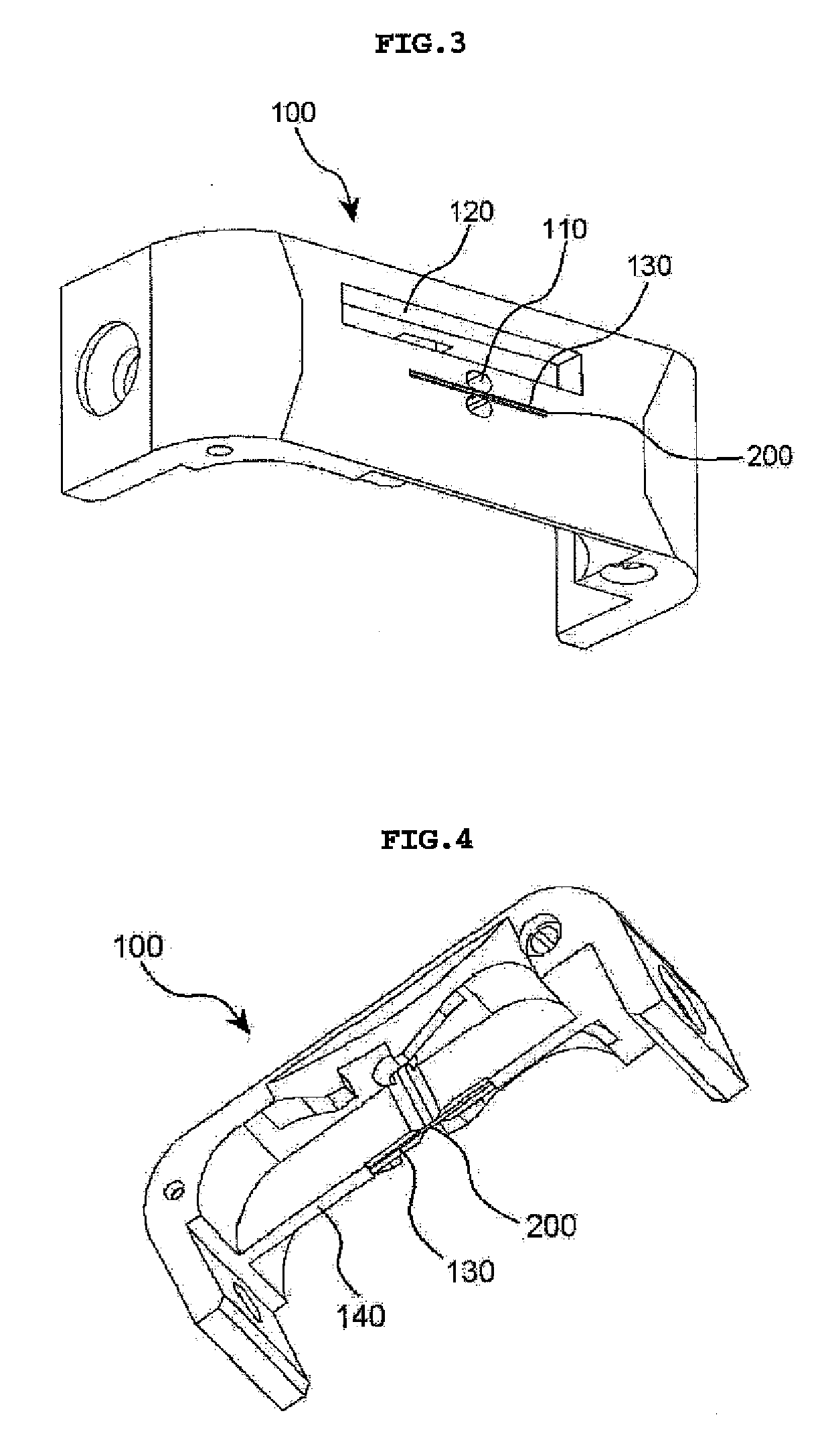
[0020]FIG. 3 is a top perspective view showing a state in which a thin plate is coupled to a needle plate for a double-needle sewing machine according to an embodiment of the present invention, and FIG. 4 is a bottom perspective view of FIG. 3. FIG. 5 is a top perspective view showing a state in which a thin plate is decoupled from a needle plate for a double-needle sewing machine according to an embodiment of the present invention, and FIG. 6 is a bottom perspective view of FIG. 5.

[0021] Referring to FIGS. 3 through 6, the needle plate 100 for a double-needle sewing machine according to an embodiment of the present invention is formed with a tr...


PUM


Abstract

Disclosed is a needle plate for a double-needle sewing machine. The needle plate includes a partition extending downward between the needle holes and provided with a thin plate insertion slit in an intermediate portion thereof, and a thin plate inserted into the thin plate insertion slit. Thus, the rigidity of a thin wall formed between the needle holes is reinforced by providing the partition and the thin plate inserted into the partition between the needle holes, so that stitches can be formed in parallel without breakage of the needle plate even when the interval between the needle holes is less than 2 mm.

Description

BACKGROUND OF THE INVENTION [0001] 1. Field of the invention [0002] The present invention relates generally to a double-needle sewing machine, and more particularly, to a needle plate for a double-needle sewing machine that sews the edge of a thick workpiece with two lines of stitches. [0003] 2. Description of the Prior Art [0004]FIGS. 1 and 2 are perspective views showing a needle plate for a conventional double-needle sewing machine. [0005] A needle plate 10 used in a conventional double-needle post bed sewing machine has two needle holes 11a formed on the cross as shown in FIG. 1 or two needle holes 11b oppositely formed in parallel as shown in FIG. 2. [0006] However, as shown in FIG. 2, on doing proximity sewing work of 2 mm or less using the later needle plate 10 in which the two needle holes 11b are opposite to each other, the interval between the two needle holes 11b is narrow, and thus the needle plate between the two needle holes 11b has been frequently broken due to interf...

Claims


Application Information

Patent Timeline
IPC IPC(8): D05B75/00
CPCD05B73/12D05B1/08D05B27/00
Inventor KIM, HYUN SUNG
Owner SUSR MACHINERY
Why Eureka
Try Eureka