
Membrane electrode assembly, fuel cell stack with membrane electrode assembly and alignment tool for fuel cell stack

Pending Publication Date: 2021-08-12
POWERCELL SWEDEN AB
View PDF2 Cites 0 Cited by
  • Summary
  • Abstract
  • Description
  • Claims
  • Application Information

AI Technical Summary

Benefits of technology

The patent text describes a new fuel cell technology that overcomes the problem of short circuits caused by contact between bipolar plates. The technology includes a membrane electrode assembly, a fuel cell stack, and an alignment tool that ensure accurate alignment of the components of the fuel cell stack and reduce the risk of short circuits. The membrane electrode assemblies extend over the bipolar plates, which ensures that they are electrically isolated from each other and prevents short circuits in the fuel cell stack.

Problems solved by technology

The disadvantage of the known alignment is that both MEA and bipolar plates have to be provided with the respective alignment features, which is very costly, and only very narrow tolerances in the manufacture of MEAs and bipolar plates are allowable.
Additionally, the stacking process is very time consuming and in case only a single bipolar plate or MEA is not properly aligned, the complete stack has to be dismissed.
Another disadvantage of the known fuel cell units it that due to the necessity of proper alignment, and due to the fact that the MEA is flexible and therefore easily bended, the MEA needs to be stabilized by the adjacent bipolar plates.
This in turn results in the risk of short circuits due to contacting bipolar plates, in case the MEA does not extend till the outer circumference of the sandwiching bipolar plates.
In case the membrane electrode assembly overlaps the bipolar plate, a correct alignment of bipolar plate and membrane electrode assembly used to be very challenging.

Method used


Image

  • Membrane electrode assembly, fuel cell stack with membrane electrode assembly and alignment tool for fuel cell stack
  • Membrane electrode assembly, fuel cell stack with membrane electrode assembly and alignment tool for fuel cell stack

Examples


Embodiment Construction

[0029]In the following same or similar functioning elements are indicated with the same reference numerals.

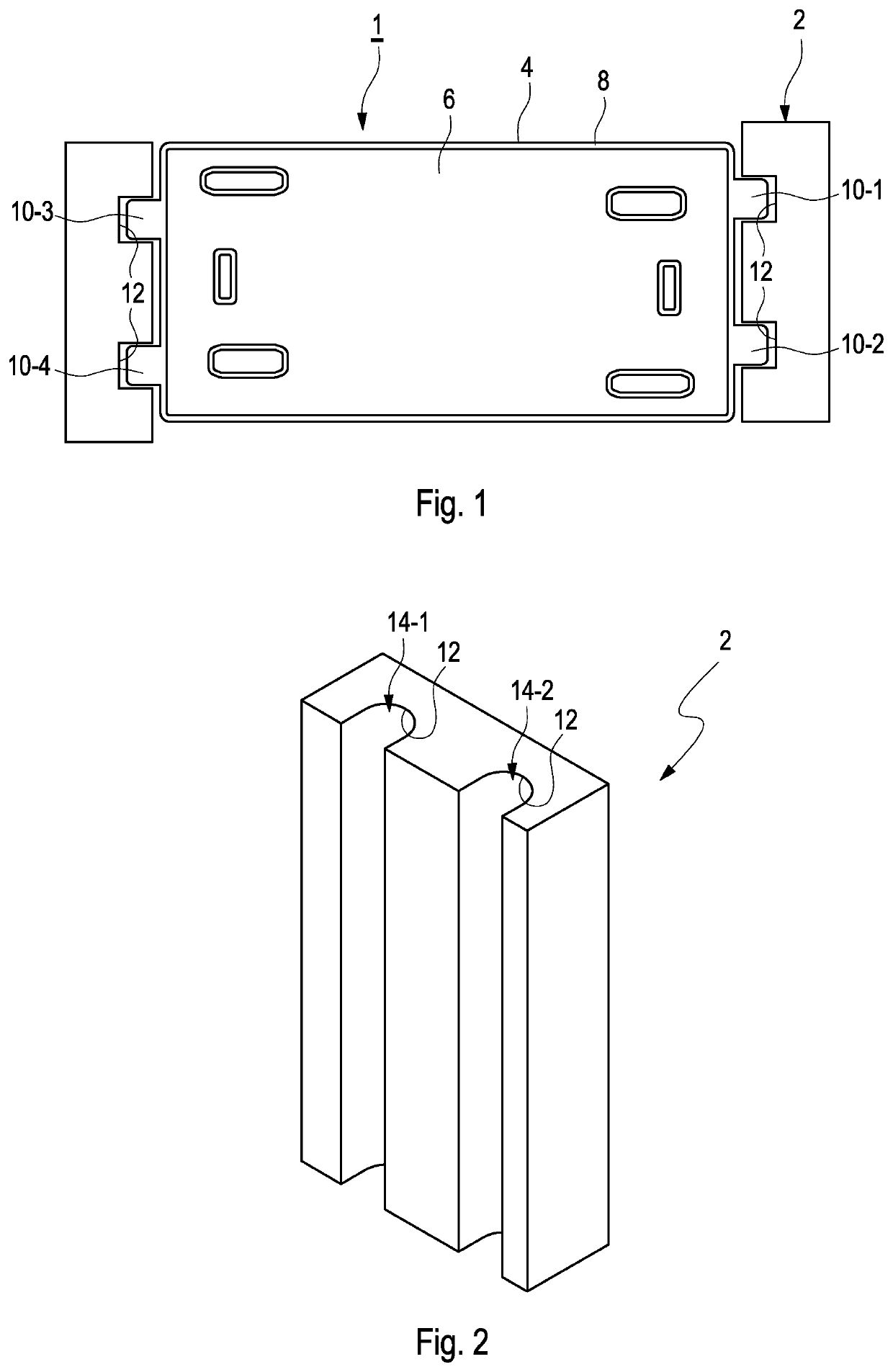
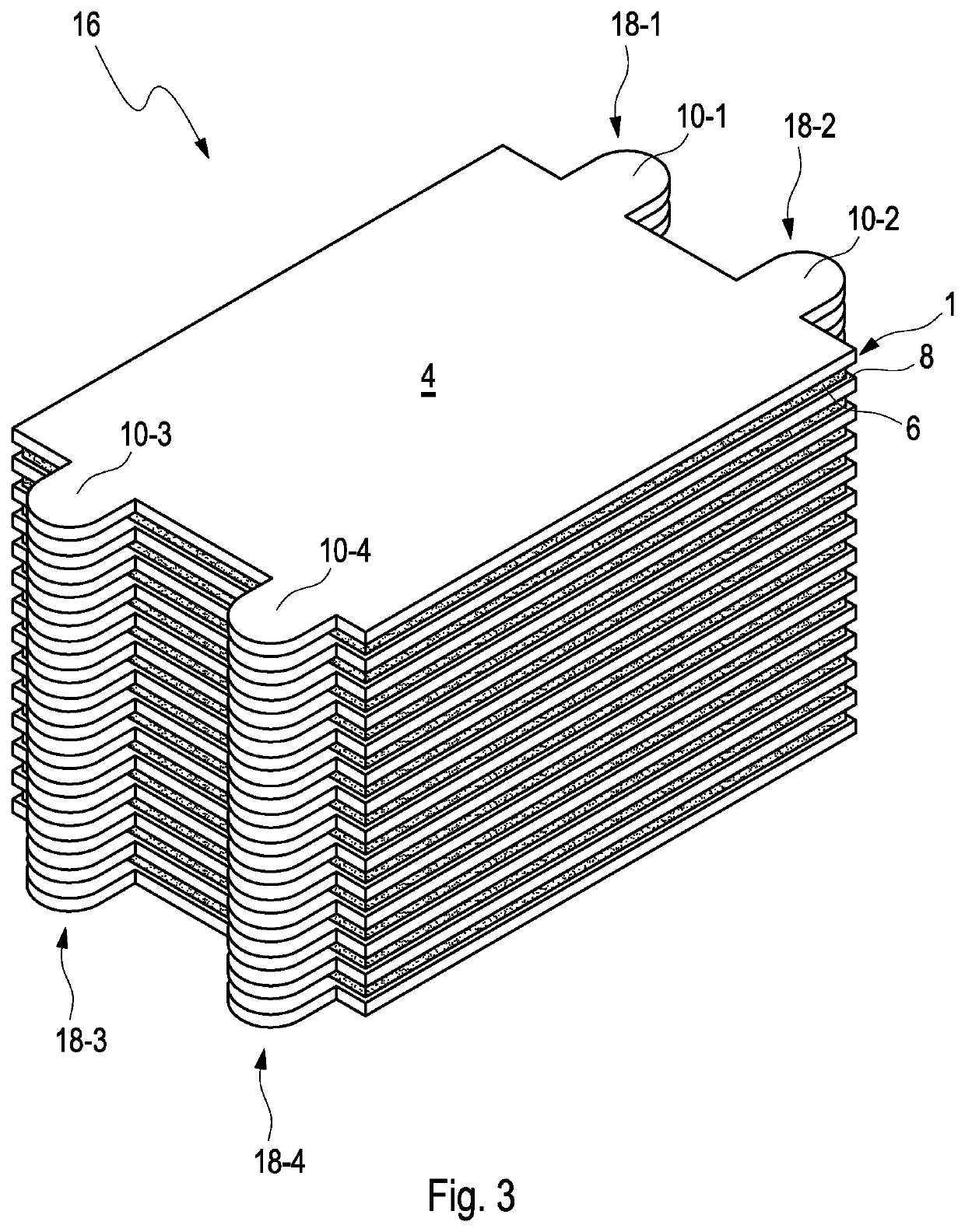
[0030]FIG. 1 shows a schematic view of a fuel cell unit 1 in an alignment tool 2, wherein the fuel cell unit 1 comprises a membrane electrode assembly 4 onto which a bipolar plate 6 is orientated. Preferably, the bipolar plate 6 has been fastened to the membrane electrode assembly 4 in a preceding preassembling step in which the membrane electrode assembly 4 and the bipolar plate are aligned and fastened to each other.

[0031]The aligning of the membrane electrode assembly 4 on one side of the bipolar plate 6 may be performed by any suitable alignment method. For example, it is possible using a camera or alignment structures, which provides a predetermined spatial orientation for the membrane electrode assembly 4 in relation to the bipolar plate 6, when the membrane electrode assembly 4 is placed on top of the bipolar plate 6 or vice versa. Of course, any other alignment procedur...


PUM


Abstract

A membrane electrode assembly for a fuel cell stack includes at least a cathode, an anode and a membrane therebetween, wherein the membrane electrode assembly further has a basic shape which substantially resembles the shape of a bipolar plate of a fuel cell unit onto which the membrane electrode assembly is intended to be placed, wherein the membrane electrode assembly further includes at least one distinctive alignment projection, which protrudes from a circumference of the basic shape and wherein the distinctive alignment projection has a size and / or shape which is adapted to be contacted by an alignment tool for aligning the membrane electrode assembly in the fuel cell stack, as well as a fuel cell stack including such a membrane electrode assembly and an alignment tool or fuel cell stack housing for aligning and / or housing such a fuel cells stack.

Description

BACKGROUND AND SUMMARY[0001]The present invention relates to a membrane electrode assembly, a fuel cell stack with such a membrane electrode assembly as well as to an alignment tool for a fuel cell stack.[0002]A fuel cell stack usually comprises two monopolar plates between which a plurality of membrane electrode assemblies is arranged, which in turn are separated by bipolar plates. The membrane electrode assembly (MEA) itself comprises at least a cathode, an anode and a membrane therebetween, for reacting hydrogen and oxygen, to electric energy and water. For providing the reactants (hydrogen and oxygen) to the respective electrodes, the bipolar plates arranged at both sides of the MEA have a fluid flow field which guides the reactants' fluid flow to the respective electrodes.[0003]Since the reaction in a single MEA typically produces insufficient voltage for operating most applications, a plurality of the MEAs is stacked and electrically connected in series to achieve a desired vo...

Claims


Application Information

Patent Timeline
IPC IPC(8): H01M8/0297H01M8/241H01M8/2404H01M8/1004
CPCH01M8/0297H01M8/1004H01M8/2404H01M8/241H01M8/2475Y02E60/50H01M8/0247H01M8/24H01M8/249H01M2008/1095H01M8/0202
Inventor MUNTHE, STEFAN
Owner POWERCELL SWEDEN AB
Learn More