Front vehicle-body structure of vehicle

Active Publication Date: 2021-09-30
MAZDA MOTOR CORP
View PDF8 Cites 3 Cited by
  • Summary
  • Abstract
  • Description
  • Claims
  • Application Information

AI Technical Summary

Benefits of technology

[0019]In the above embodiments, the side frame portion includes, on a vehicle-width-direction outer side of the first bead portion, a convex second bead portion extending in the front-rear direction and protruding downward. This configuration allows for effectively reinforcing rigidity of the side frame portion without the need for additional reinforcement members.
[0020]In the above embodiments, at least a part of the damper member is disposed between the first bead portion and the second bead portion in plan view. This configuration increases shock absorption performance by spacing the damper member and the inner panel from each other, improving pedestrian protection performance.
[0021]In the above embodiments, the side frame portion is formed to have a reduced vehicle-width-direction dimension from a rear end thereof to the damper mounting portion, and a distance between the first and second bead portions in the vehicle width direction is smaller toward a front side, and the first and second bead portions are connected at front ends thereof. By reducing the gap between the first and second bead portions in the vehicle width direction, this configuration ensures rigidity of a portion with a small

Problems solved by technology

In the case of a vehicle equipped with a large bonnet, an operation of opening the bonnet is burdensome for occupants.
If a gap occurs at the parting portion due to positional displacement, it not only greatly degrades appearance (how the vehicle looks) but also invites the possibility of rain water and the like entering the engine room through the gap.
Hence, providing a damper member, which urges the bonnet from a closed position toward an opening portion, to improve the easiness in operating the bonnet may degrade the appearance of the vehicle.
In other words, as urging force of the damper member toward a vehicle-width-direction outer front side is applied to the damper mounting portion o

Method used


Image

  • Front vehicle-body structure of vehicle
  • Front vehicle-body structure of vehicle
  • Front vehicle-body structure of vehicle

Examples


Example

First Embodiment

[0038]Below a description will be given of a first embodiment of the present disclosure with reference to FIGS. 1 to 12.

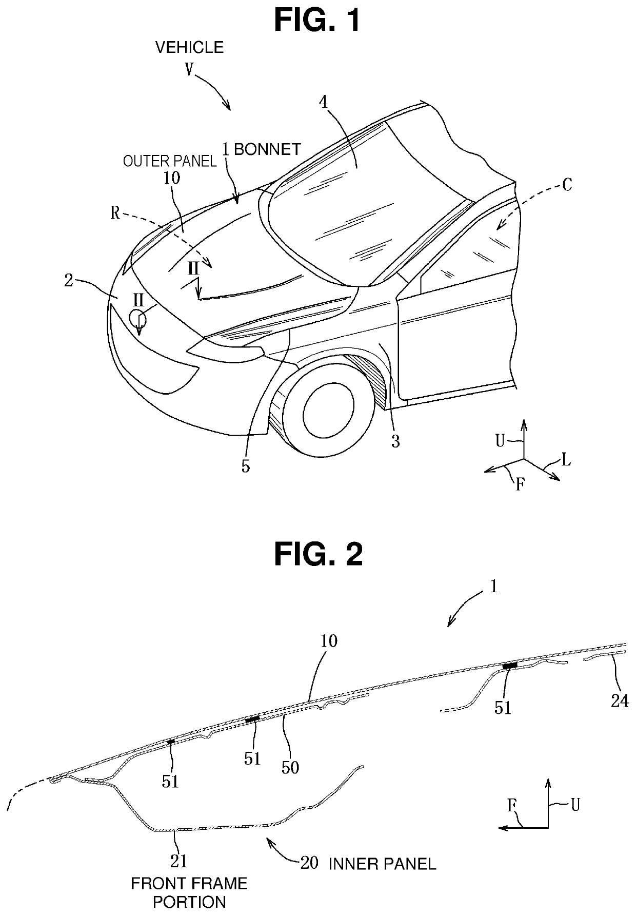
[0039]As shown in FIG. 1, a vehicle V according to the first embodiment incudes a bonnet 1 that openably and closably covers a portion above an engine room R formed in front of a vehicle cabin C in which occupants are accommodated. The engine room R is defined by a space that is delimited by a front bumper 2 disposed at a front end of a vehicle body, a pair of left and right front fender panels (hereinafter each abbreviated as a front fender) 3 extending rearward from left and right ends, respectively, of the front bumper 2, and a dash panel (not shown) supporting a lower end of a windshield 4 and constituting a front wall of the vehicle cabin. A parting portion 5 extending back and forth is formed at a boundary between a vehicle-width-direction end of the bonnet 1 and an upper end of the front fender 3. In the drawings as referred to in the followi...


PUM


Abstract

A front vehicle-body structure of a vehicle ensures good vehicle appearance and ease in operating a bonnet without increasing the vehicle body weight. The front vehicle-body structure includes a bonnet including outer and inner panels, a hinge supporting the bonnet such that the bonnet can open and close, and a damper member urging the bonnet. The inner panel includes front and rear frame portions, and a pair of side frame portions respectively connecting left and right ends of the front and rear frame portions and each including a hinge mounting portion and a damper mounting portion for mounting the damper member frontward of the hinge mounting portion. The side frame portion includes a convex first bead portion formed partially in a curved shape between the hinge mounting portion and the damper mounting portion and extending back and forth from the hinge mounting portion to the damper mounting portion.

Description

BACKGROUNDTechnical Field[0001]The present disclosure relates to a front vehicle-body structure of a vehicle, in particular to a front vehicle-body structure of a vehicle including a hinge that supports a bonnet such that the bonnet can open and close and a damper member that urges the bonnet from a closed position toward an open position.Background Art[0002]A front vehicle-body structure has been conventionally known that includes a bonnet including a bonnet outer panel (hereinafter abbreviated as an outer panel) and a bonnet inner panel (hereinafter abbreviated as an inner panel) attached to a back side of the outer panel; and a hinge supporting the bonnet such that the bonnet can open and close relative to an opening above an engine room formed in a vehicle body.[0003]In the case of a vehicle equipped with a large bonnet, an operation of opening the bonnet is burdensome for occupants. Hence, a damper member for always urging the bonnet from a closed position toward an opening pos...

Claims


Application Information

Patent Timeline
IPC IPC(8): B62D25/12B62D25/10
CPCB62D25/12B62D25/10B62D25/105
Inventor ONAKA, YASUYUKIOKADA, SHOGOMITOMA, YUTAKA
Owner MAZDA MOTOR CORP
Why Eureka
Try Eureka