Industrial two-layer fabric

Active Publication Date: 2007-05-03
NIPPON FILCON
View PDF27 Cites 13 Cited by
  • Summary
  • Abstract
  • Description
  • Claims
  • Application Information

AI Technical Summary

Benefits of technology

[0008] An object of the present invention is to provide an industrial two-layer fabric capable of satisfying all the properties that an industrial fabric must have such as dehydration property, surface property and rigidity.
[0016] The industrial two-layer fabric of the present invention has one upper surface side warp and three warp binding yarns adjacent thereto which get together to form on the upper side surface a design corresponding to a warp. Since the design and knuckle height of the fabric is uniform, the fabric has an excellent surface property. In addition, owing to existence of many spaces in the diagonal direction in the fabric layer compared with the conventional fabric, it has excellent breathability and water drainage property.

Problems solved by technology

In recent years, owing to the speed-up of a papermaking machine, requirements for papermaking wires become severe further.
In addition, warp binding yarns forming a pair adjacently cross each other in the fabric layer so that they may block an internal space in the layer and partially cause insufficient dehydration.
Thus, fabrics capable of satisfying all the properties that an industrial fabric is required to have such as dehydration property, surface property and rigidity have not yet been developed.

Method used


Image

  • Industrial two-layer fabric
  • Industrial two-layer fabric
  • Industrial two-layer fabric

Examples


example 1

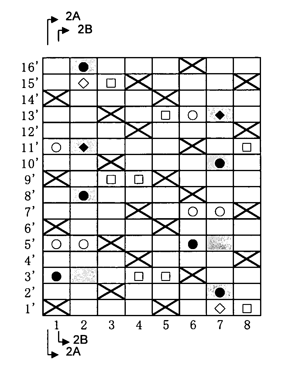
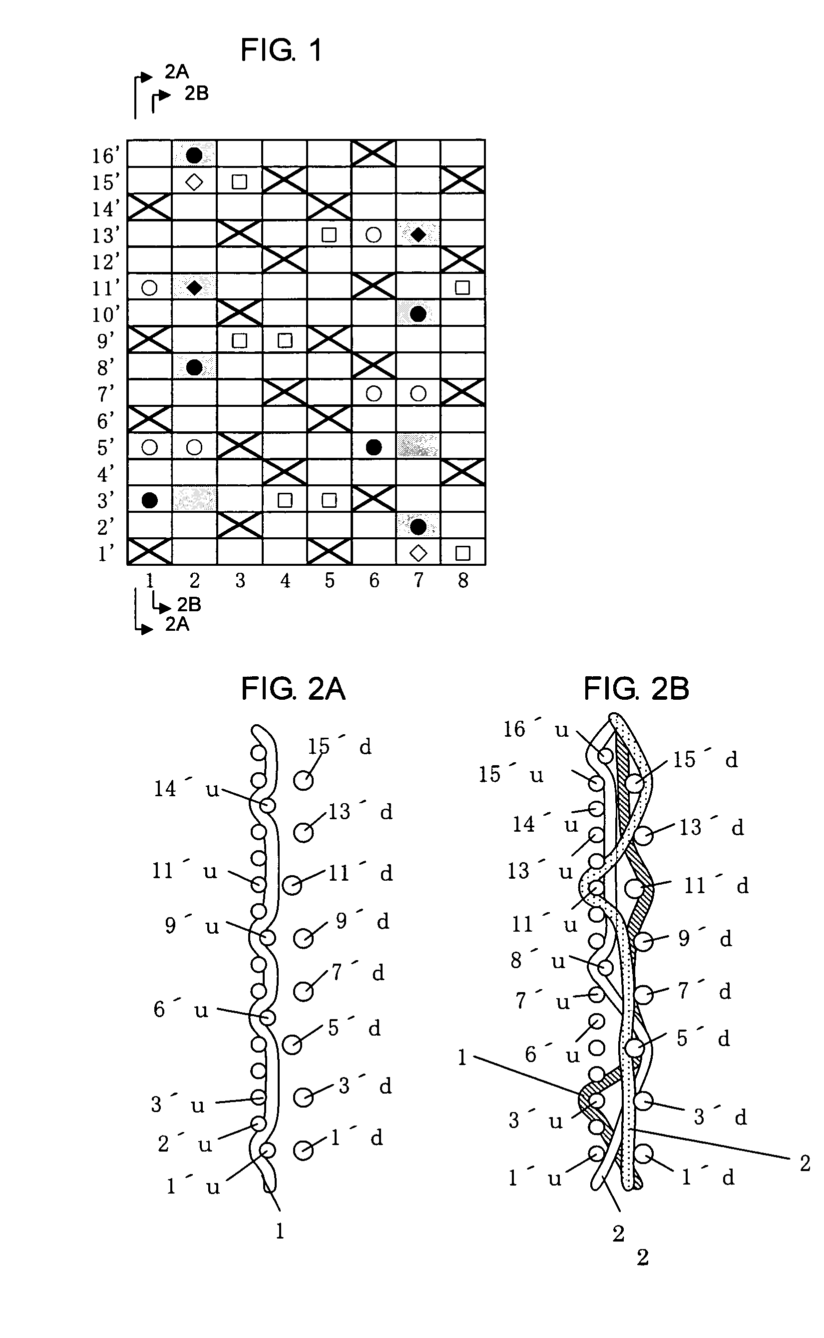
[0073]FIG. 1 is a design diagram of a fabric of Example 1 of the present invention. FIGS. 2A and 2B include cross-sectional views taken along the line 2A-2A of an upper surface side warp 1 and that of a warp binding yarn 1 and a cross sectional view taken along the line 2B-2B of two warp binding yarns 2 respectively, each illustrated in the design diagram of FIG. 1. FIG. 3 is a plan view, viewed from the upper surface side, of a fabric woven based on the design diagram of FIG. 1. For convenience of explanation, indicated at numeral 1 in the design diagram of FIG. 1 are both warp 1 and warp binding yarn 1, which is also applicable to numeral 6. Warp 2 means two warp binding yarns, which is also applicable to warp 7. This fabric is a 16-shaft two-layer fabric having two sets of one upper surface side warp and three warp binding yarns. Warps 1 and 2 constitute one set, while warps 6 and 7 constitute another one set. The other warps 3, 4, 5 and 8 are each a warp set composed of an upper...

example 2

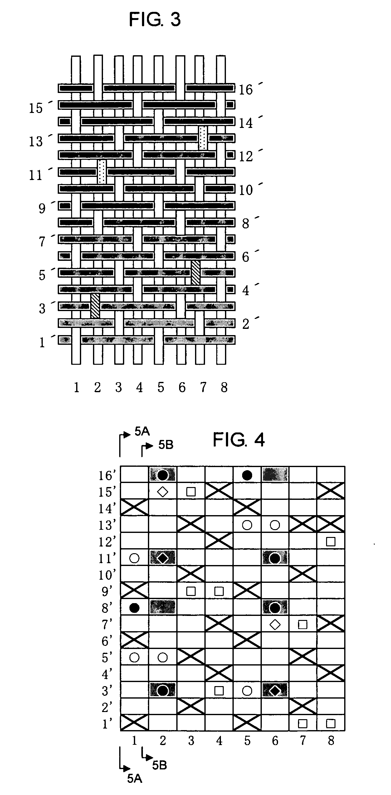
[0086]FIG. 4 is a design diagram of a fabric of Example 2 according to the present invention. FIGS. 5A and 5B include cross-sectional views of an upper surface side warp 1 and that of a warp binding yarn 1 and two warp binding yarns 2, each illustrated in the design diagram of FIG. 4, and these three warp binding yarns get together and form a design corresponding to a warp on the upper side surface. In the design diagram of FIG. 4, indicated at numerals 1 and 5 are pairs of an upper surface side warp and a warp binding yarn, indicated at numerals 2 and 6 are pairs of two warp binding yarns, and indicated at numerals 3, 4, 7 and 8 are pairs of an upper surface side warp and a lower surface side warp.

[0087] The upper side surface is composed of warps having a ¼-½ design and wefts having a ⅓ design, as in Example 1. Each of the warp binding yarn 1 and two warp binding yarns 2 does not constitute a ¼-½ design on the upper side surface, but they get together and cooperatively form a ¼-½...

example 3

[0090]FIG. 6 is a design diagram of a fabric of Example 3 according to the present invention. FIGS. 7A and 7B include cross-sectional views of an upper surface side warp 1 and that of a warp binding yarn 1 and two warp binding yarns 2, each illustrated in the design diagram of FIG. 6. These three warp binding yarns get together and form a design corresponding to a warp on the upper side surface. In the design diagram of FIG. 6, indicated at numerals 1 and 5 are pairs of an upper surface side warp and a warp binding yarn, indicated at numerals 2 and 6 are pairs of two warp binding yarns, and indicated at numerals 3, 4, 7 and 8 are pairs of an upper surface side warp and a lower surface side warp.

[0091] The upper side surface is composed of warps having a ¼-½ design and wefts having a ⅓ design, as in Example 1. Each of the warp binding yarn 1 and two warp binding yarns 2 does not constitute a ¼-½ design on the upper side surface, but they get together and cooperatively form a ¼-½ des...


PUM


Abstract

In an industrial two-layer fabric, one upper surface side warp and three warp binding yarns are disposed adjacent to each other. Each of the three warp binding yarns appears on the upper side surface in turn and passes over different one or two successive upper surface side wefts. At least one upper surface side weft exists between knuckles formed on the upper side surface by the three warp binding yarns. Adjacent to the upper surface side warp, these three warp binding yarns get together to form on the upper side surface a design which is the same design formed by an upper surface side warp.

Description

TECHNICAL FIELD [0001] The present invention relates to an industrial two-layer fabric having especially excellent breathability, surface property and fabric rigidity. [0002] Background Art [0003] Fabrics woven with warps and wefts have conventionally been used widely as an industrial fabric. They are used in various fields including papermaking wires, conveyor belts and filter cloths and required to have fabric properties suited for the intended use or using environment. Of such fabrics, a papermaking wire used in a papermaking step for removing water from raw materials by making use of the meshes of a fabric must satisfy severe requirements. There is therefore a demand for the development of fabrics which hardly transfer their wire marks to paper and therefore have an excellent surface property, have a dehydration property for sufficiently removing unnecessary water contained in the raw materials, have enough wear resistance and rigidity to permit desirable use even under severe e...

Claims


Application Information

Patent Timeline
IPC IPC(8): D03D25/00
CPCD03D11/00D21F1/0036
Inventor UEDA, IKUO
Owner NIPPON FILCON
Why Eureka
Try Eureka