Pressure pickup heating bar, in particular for a pressure pickup glow plug

a technology of pressure pickup and heating bar, which is applied in the direction of mechanical equipment, machines/engines, light and heating apparatus, etc., to achieve the effect of low cost and simple design

Inactive Publication Date: 2007-05-03
BERU AG DE
View PDF9 Cites 22 Cited by
  • Summary
  • Abstract
  • Description
  • Claims
  • Application Information

AI Technical Summary

Benefits of technology

[0008] Thus, it is a primary object of the present invention to create a pressure pickup heating bar, in particular, for a pre...

Problems solved by technology

Due to the voluminous geometry and the weight of the pressure or load transmission devices relative to the pressure sensor, in these kn...

Method used


Image

  • Pressure pickup heating bar, in particular for a pressure pickup glow plug

Examples


Embodiment Construction

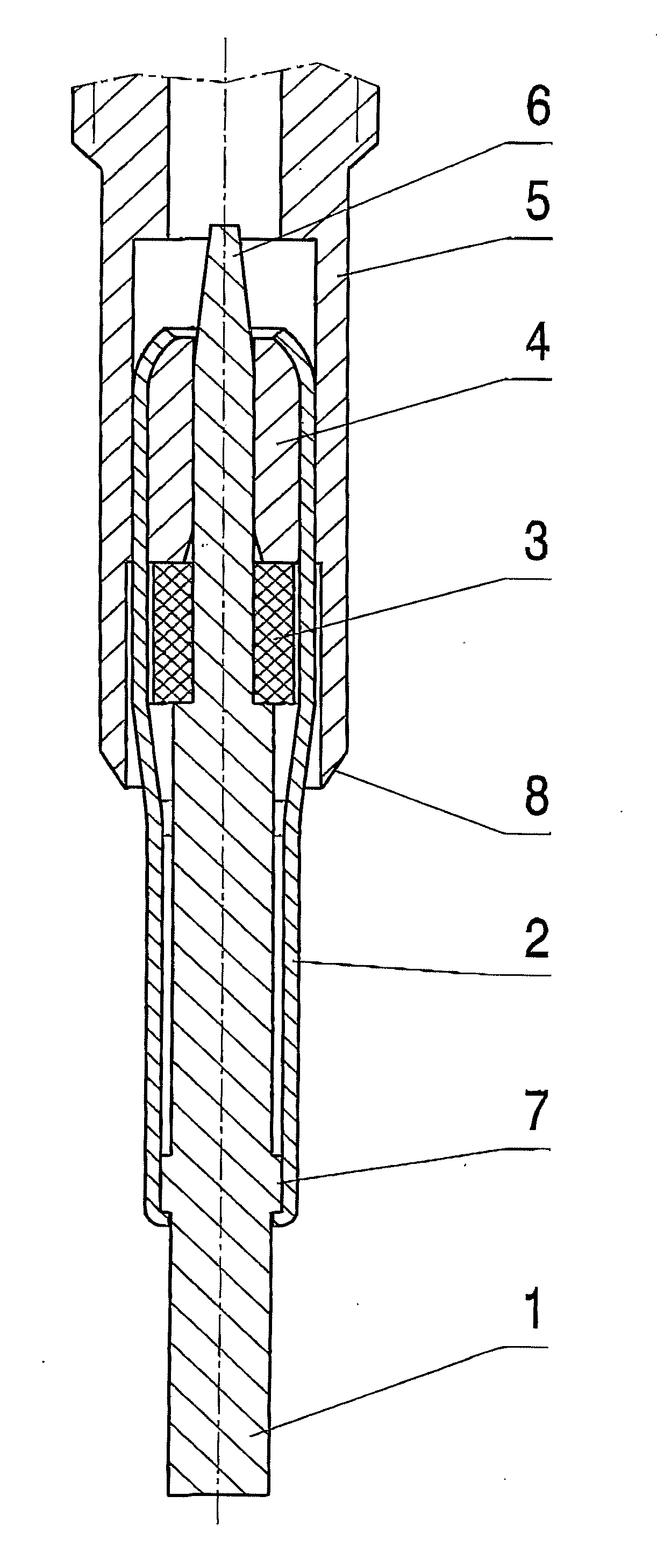
[0014] The pressure pickup glow plug part shown in the drawing essentially comprises a heating bar 1, 2, 3, 4, which is arranged in a glow plug body 5 such that the pressure pickup glow plug part axially projects from the glow plug body 5 at the combustion chamber end. The glow plug body 5 is sealed off from the cylinder head of the internal combustion engine by a seal seat 8.

[0015] The heating bar 1, 2, 3, 4, comprises a heating element 1, which is preferably made of a ceramic material, and of a support tube 2 that encompasses the heating element 1 on the outside and with a degree of clearance in the part on the combustion chamber. A pressure sensor 3, which can, for example, be a piezoelectric element, and which, in response to mechanical stress, generates an electrical signal, is arranged on the heating element 1, with a clearance between it and the support tube 2 such that pressure that is present in the combustion chamber end of the heating bar is transferred to the pressure s...


PUM


Abstract

A pressure pickup heating bar, in particular for a pressure pickup glow plug, having an electrical heating element ( 1 ) and a pressure sensor ( 3 ) onto which the pressure present at the heating bar ( 1 ) is transmitted. The heating bar has a support tube ( 2 ) which encompasses the heating element ( 1 ) on the outside with an axial pretension. A pressure sensor ( 3 ) is arranged between the heating element ( 1 ) and the support tube ( 2 ) and is subjected to pressure that is present on the heating bar.

Description

BACKGROUND OF THE INVENTION [0001] 1. Field of the Invention [0002] The invention relates to a pressure pickup heating bar, in particular for a pressure pickup glow plug, comprising an electrical heating element and a pressure sensor onto which the pressure present at the heating element is transmitted. [0003] 2. Description of the Related Art [0004] A pressure pickup heating bar or a pressure pickup glow plug with such a heating bar is used in the case of self-igniting internal combustion engines; apart from the normal glow function, a pressure pickup heating bar or a pressure pickup glow plug with such a heating bar also has a pressure pickup function, by way of which, for example, the pressure present in the cylinder of the internal combustion engine can be determined. [0005] Commonly used pressure pickup glow devices comprise a heating bar and a pressure sensor that is pressurized by the pressure present in the cylinder of the internal combustion engine, which pressure is transm...

Claims


Application Information

Patent Timeline
IPC IPC(8): F23Q7/00F23Q7/22
CPCF02P19/028F23Q7/001F23Q2007/002
Inventor LAST, BERND
Owner BERU AG DE
Why Eureka
Try Eureka