Powered attachment for a wheelchair

Inactive Publication Date: 2007-05-03
KNAUB JAMES
View PDF22 Cites 40 Cited by
  • Summary
  • Abstract
  • Description
  • Claims
  • Application Information

AI Technical Summary

Benefits of technology

[0012] Preferably the crossbar mounting means uses a ball lock pin for locking to the crossbar. As such, the crossbar may be removed from the wheelchair relatively easily by manually releasing the ball lock pin. Accordingly, it is relatively easy to convert the wheelchair into a powered vehicle, and vice versa, manually without requiring the use of tools.
[0013] The center bar is fixed at one end thereof proximate to a center point of the crossbar and terminates at the other end thereof at a front wheel post support. The center bar includes a

Problems solved by technology

Such devices are useful for extending the distance a person may travel without tiring, as manually propelling a wheelchair is a laborious task.
However, such devices are relatively difficult to detach from the wheelchair to which they are mounted, as is often desired in closed or tight spaces such as indoors.
To the extent that such devices are usable indoors, however, such devices are not capable of powering the wheelchair to which they are attached to any significant distance or at a significant speed.
Prior art devices of this type are characterized by a compact, relatively small drive wheel, and as such they are limited both in the safe maximum speed at which they can operate, and the irregularity of the surface over which they can travel.
None of these prior art devices would be suitable, for example, traveling over a gravel or dirt path.
In open or outdoor situations, such as when a person desired to travel to a local supermarket several blocks away, for example, such prior art devices do not provide enough speed to make the trip a practical, short expedition.
Such devices typically ca

Method used


Image

  • Powered attachment for a wheelchair
  • Powered attachment for a wheelchair
  • Powered attachment for a wheelchair

Examples


Embodiment Construction

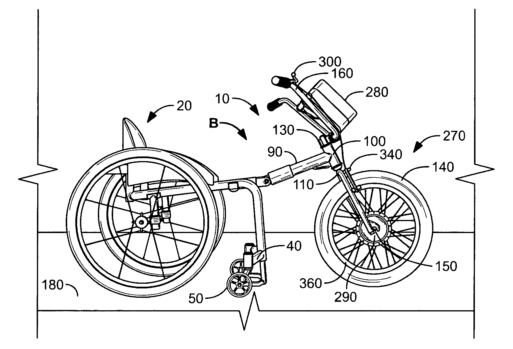
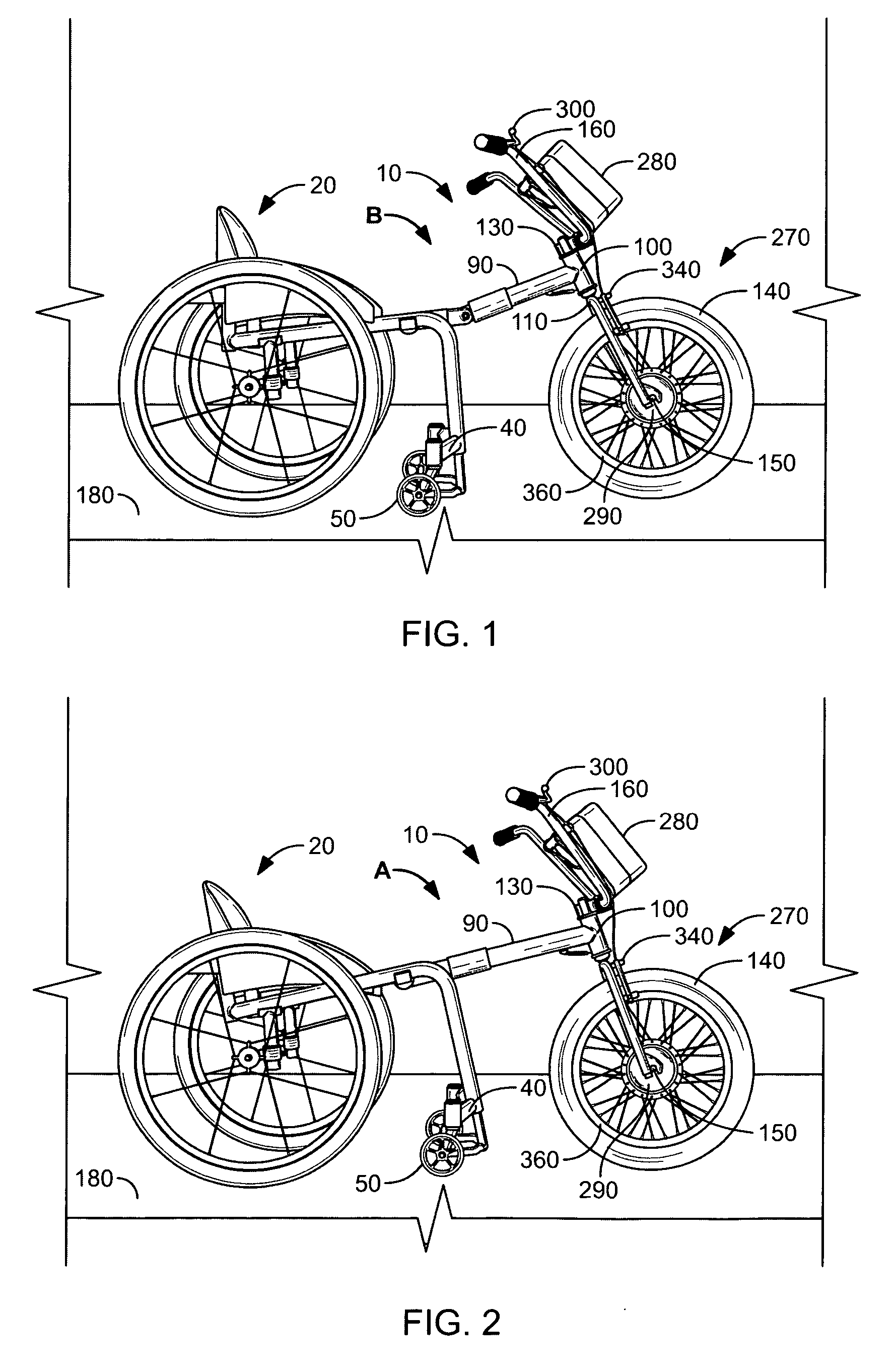
[0026]FIG. 1 illustrates an improvement 10 for a wheelchair 20 of the type having a pair of generally parallel support bars 30 (FIGS. 3 and 4), a footrest 40, and a plurality of footrest supporting wheels 50. For example, a wheelchair 20 sold under the brand name “Typhoon W.K.-'00” is well-suited for use with the improvement 10 of the present invention.

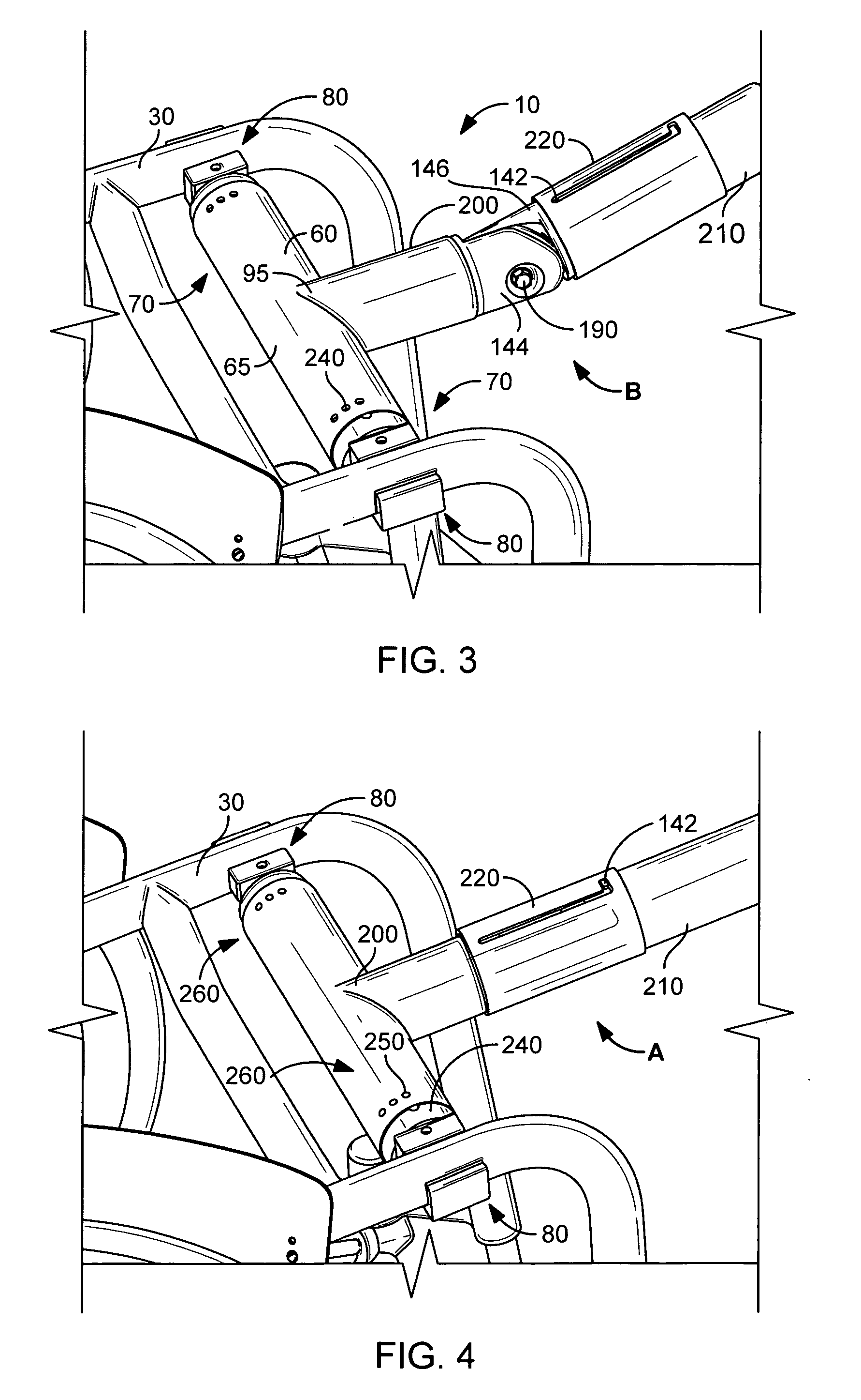
[0027] The improvement 10 is comprised of generally a crossbar 60 (FIG. 3 and 4), a center bar 90, a front wheel post 100 which includes forks 110, a front wheel 140, and a handlebar means 160. Each end 70 of the crossbar 60 is connected to one of the support bars 30 of the wheelchair 20 with a crossbar mounting means 80 (FIGS. 5 and 6). The crossbar mounting means 80 is preferably a split clamp 81 commonly used to fix items to tubular bars (FIG. 5). The split clamp 81 preferred in the present invention comprises an outer clamp 82 and an inner clamp 84 bolted to each other through mounting holes 86 using an Allan-head bolt with a Nyl...


PUM


Abstract

Disclosed is an improvement for a wheelchair of the type having a pair of generally parallel support bars, a footrest, and a plurality of footrest supporting wheels. The improvement comprises a crossbar, a center bar, a front wheel post, a front wheel, and a handlebar. Each end of the crossbar is connected to one of the support bars of the wheelchair with a crossbar mounting. The center bar is fixed at one end thereof proximate to a center point of the crossbar and terminates at the other end thereof at a front wheel post support which rotationally captures the front wheel post. A lower end of the front wheel post terminates in a pair of generally parallel fork posts between which the front wheel is axially mounted. A powered driving means rotationally drives the front wheel and is controlled by a throttle mounted on the handlebar. The handlebar is fixedly attached to a handlebar support of an upper end of the front wheel post. The center bar includes a pivoting joint for allowing the improvement to assume a linear operating position, whereby the footrest support wheels of the wheelchair are raised off of a ground surface and the combination of the wheelchair and the improvement act as a powered trike. The center bar may also assume a non-operating means whereby the footrest support wheels of the wheelchair contact the ground, thereby allowing the cross bar of the improvement to be manually disengaged from the wheelchair so that the wheelchair may be used traditionally.

Description

[0001] This Application claims the benefit pursuant to 35 U.S.C. 119(e) of U.S. Provisional Patent Application Ser. No. 60 / 726,850 filed by the applicant on Oct. 14, 2005FIELD OF THE INVENTION [0002] This invention relates to wheelchairs and, and more particularly, to a powered attachment for a wheelchair. DISCUSSION OF RELATED ART [0003] Means for providing auxiliary power to a manually-driven wheelchair are known in the art. Such devices are useful for extending the distance a person may travel without tiring, as manually propelling a wheelchair is a laborious task. Examples of such devices are found in the following prior art patents: Patent NumberInventorPub. DateU.S. Pat. No. 6,766,871SawyerJul. 27, 2004U.S. Pat. No. 6,729,422Chu et al.May 4, 2004U.S. Pat. No. 5,651,422CasaliJul. 29, 1997U.S. Pat. No. 5,494,126MeekerFeb. 27, 1996U.S. Pat. No. 5,113,959Mastov et al.May 19, 1992U.S. Pat. No. 5,050,695Kleinwolterink, Jr.Sep. 24, 1991U.S. Pat. No. 5,016,720CokerMay 21, 1991U.S. Pa...

Claims


Application Information

Patent Timeline
IPC IPC(8): A61G5/10
CPCA61G5/042A61G5/047A61G2005/1051A61G5/1051
Inventor KNAUB, JAMES
Owner KNAUB JAMES
Why Eureka
Try Eureka