

Switching LED driver
- Summary
- Abstract
- Description
- Claims
- Application Information
AI Technical Summary
Benefits of technology
Problems solved by technology
Method used
Image

Examples
Embodiment Construction
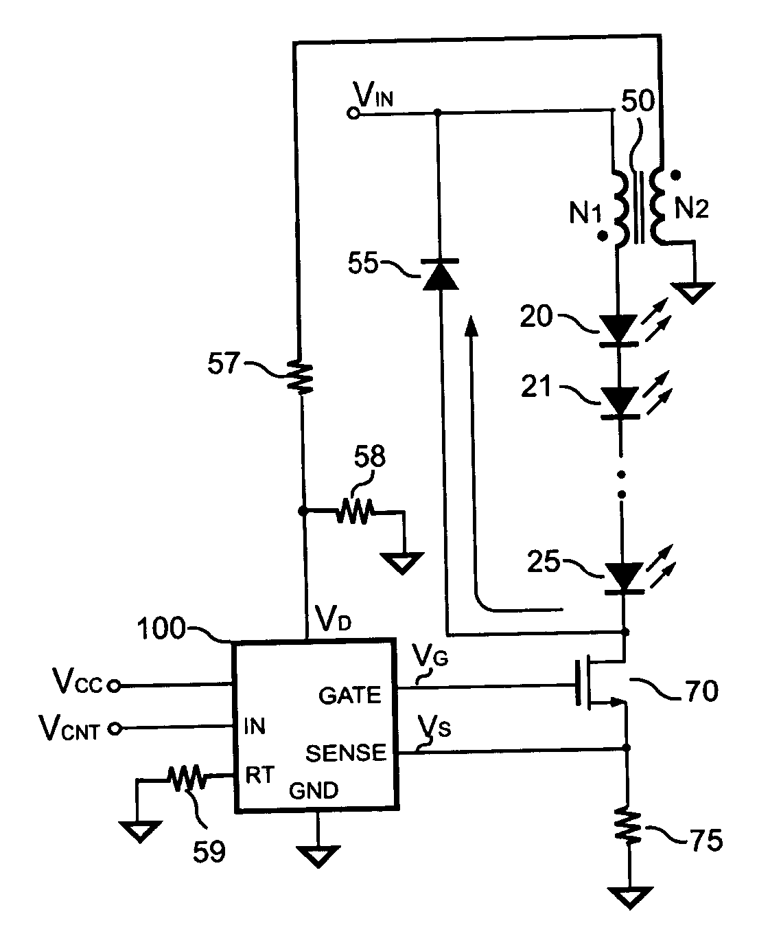
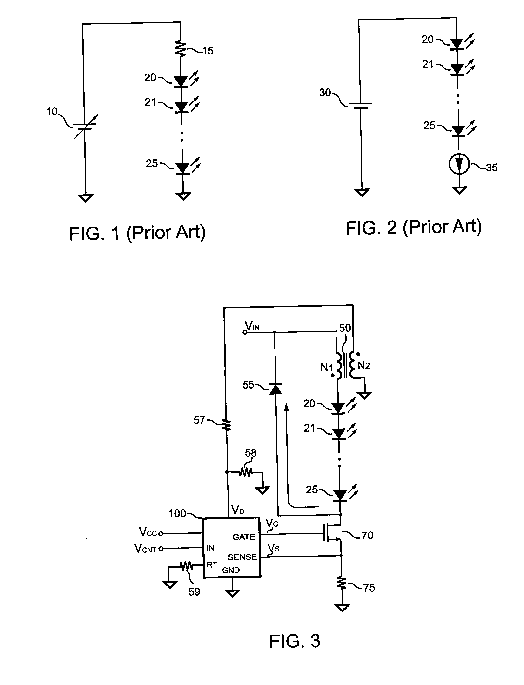
[0020]FIG. 3 shows a switching LED driver in accordance with present invention, in which a first winding N1 of a inductor 50 is coupled in series with the LEDs 20˜25. The first winding N1 of the inductor 50 includes an inductance. Further, a switch 70 is connected in series with the LEDs 20˜25 and the first winding N1 of the inductor 50 for controlling the LED current. The LED current is further converted to a current signal VS coupled to a control circuit 100 via a resistor 75. The control circuit 100 is further coupled to a second winding N2 of the inductor 50 to receive the reflected signal of the inductor 50 through resistors 57 and 58. A diode 55 is coupled in parallel to the LEDs 20˜25 and the inductor 50. Once the switch 70 is turned off, the energy of the inductor 50 is discharged through the LEDs 20˜25 and the diode 55. Meanwhile the forward voltage of the LEDs 20˜25 is reflected to the secondary winding N2 of the inductor 50. Therefore the reflected signal of the inductor ...
PUM
 Abstract
Description
Claims
Application Information