
Bulb with light emitting diodes

Inactive Publication Date: 2007-05-03
YANG SHENG LI
View PDF8 Cites 77 Cited by
  • Summary
  • Abstract
  • Description
  • Claims
  • Application Information

AI Technical Summary

Benefits of technology

[0006] The primary objective of the present invention is to provide a LED bulb with a simple assembling process.

Problems solved by technology

It raises the cost for replacement.
This process is difficult and has higher cost, so that the LED bulbs can't be provided to consumers with lower price.

Method used


Image

  • Bulb with light emitting diodes
  • Bulb with light emitting diodes
  • Bulb with light emitting diodes

Examples


Embodiment Construction

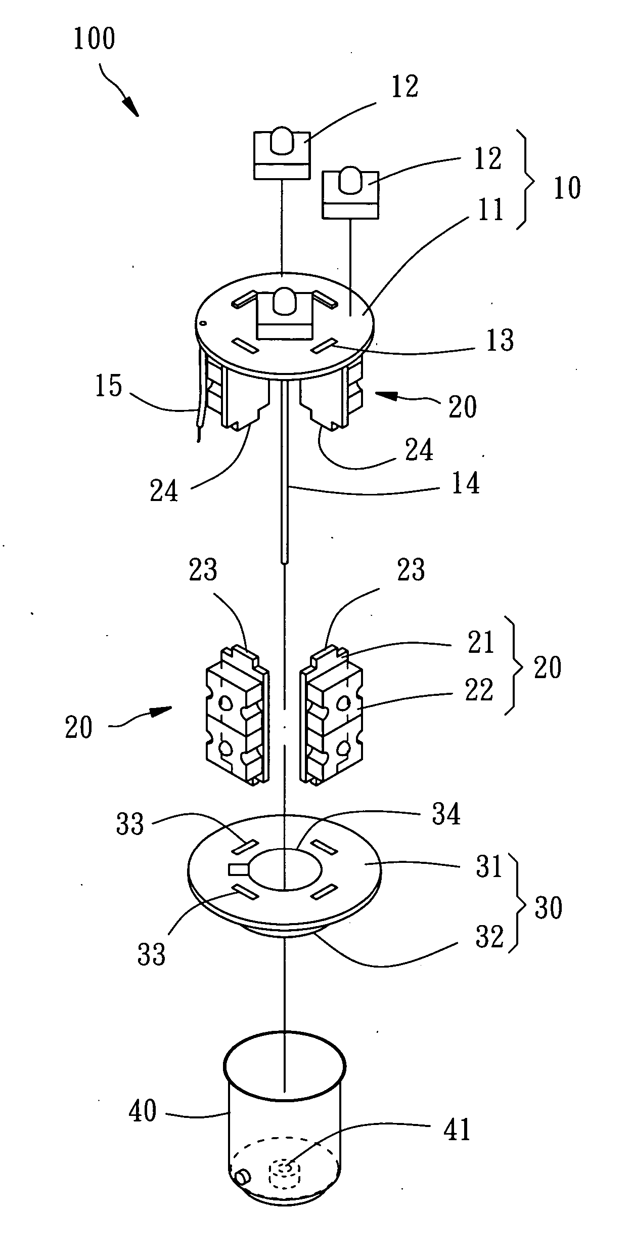
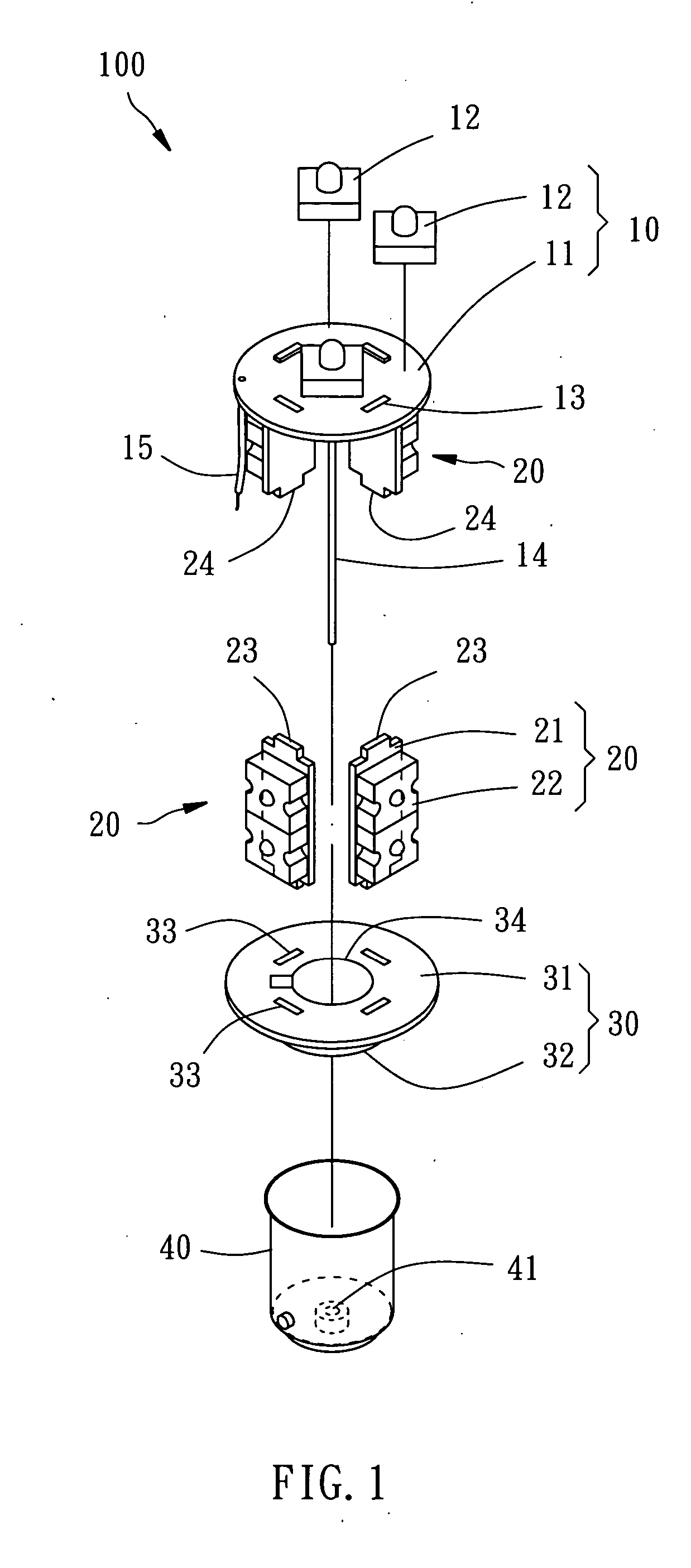
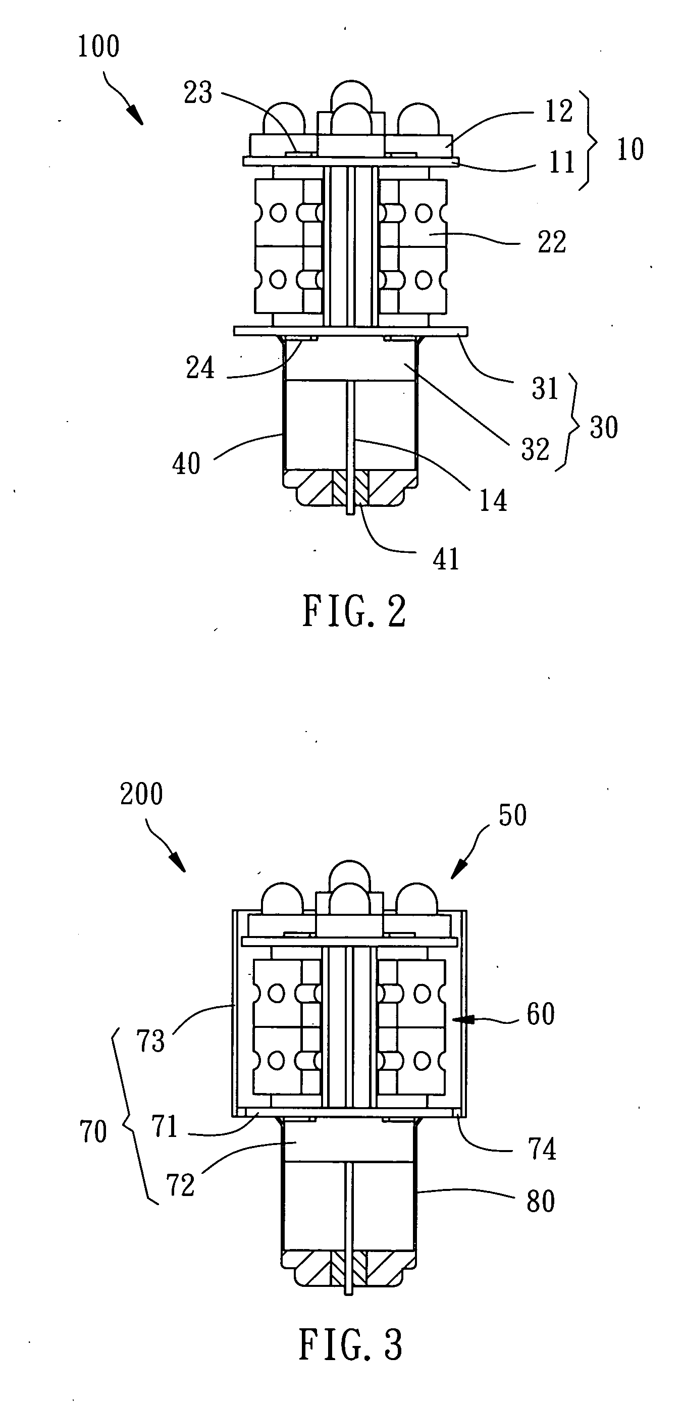
[0011] As shown in FIGS. 1 to 2, a bulb with light emitting diodes (LEDs) 100 of the first preferred embodiment of the present invention mainly comprises a top light-emitting module 10, a plurality of vertical light-emitting modules 20, a positioning base 30, and a cap 40.

[0012] The top light-emitting module 10 has a top circuit board 11 and a plurality of light emitting diodes (LEDs) 12. The top circuit board 11 substantially is a disk-like member having a predetermined conductor pattern (not shown) and a plurality of first lock slots 13 with a predetermined interval therebetween. There is a predetermined interval between the neighboring first slots 13. The LEDs 12 are connected to a top side of the top circuit board 11 and electrically connected to the conductor pattern. The top circuit board 11 is provided with wires 14 and a ground wire 15 on a bottom side thereof.

[0013] Each of the vertical light-emitting modules 20 has a vertical circuit board 21 and a plurality of LEDs 11. ...


PUM


Abstract

A bulb includes a top light-emitting module having a top circuit board and light emitting diodes (LEDs). The top circuit board has first lock slots and wires electrically connected to the LEDs respectively. Vertical light-emitting modules have a vertical circuit board with a first coupling portion and a second coupling portion and LEDs respectively. The first coupling portions are inserted into the first lock slots of the top light-emitting module. A positioning base has a positioning plate and a coupling portion. The positioning plate has second lock slots to engage the second coupling portions respectively. The positioning base has a through hole through the positioning plate and the coupling portion for the wires passing through. A cap is fixed to the coupling portion of the positioning base, and the wires through the through hole are electrically connected to a bottom of the cap.

Description

BACKGROUND OF THE INVENTION [0001] 1. Field of the Invention [0002] The present invention relates generally to a LED lamp, and more particularly to a bulb with light emitting diodes (LEDs). [0003] 2. Description of the Related Art [0004] As the improvement of technique, there are high-luminance light emitting diodes (LED) in the present market, and such LEDs are broadly applied to various products, such as interior lights and taillight of automobile. [0005] LED has to be connected to the socket for LED only, and it can't be connected to the socket for tungsten lamp directly. Therefore, while user wants to replace tungsten lamp with LED, both of the lamp and the socket have to be replace together. It raises the cost for replacement. Some improved LED is provided, which can be connected to the socket for tungsten lamp directly, such that it can reduce the cost to replace tungsten lamp with LED. Such new LED bulb has vertical plates, on which LEDs are provided, with two ends inserted i...

Claims


Application Information

Patent Timeline
IPC IPC(8): B60Q1/26
CPCF21Y2101/02F21Y2111/005F21K9/13F21V23/002F21V23/06F21K9/23F21Y2115/10F21Y2107/30
Inventor YANG, SHENG-LI
Owner YANG SHENG LI
Learn More