Combined battery pack and assembly method thereof
An assembly method and battery pack technology, which are applied in the direction of assembling battery machines, battery pack components, and isolation of batteries from their environment, etc., can solve the problem of low battery stability, achieve a simple and fast assembly process, improve assembly efficiency, and ensure stable performance. Effect
- Summary
- Abstract
- Description
- Claims
- Application Information
AI Technical Summary
Problems solved by technology
Method used
Image
Examples
Embodiment 1
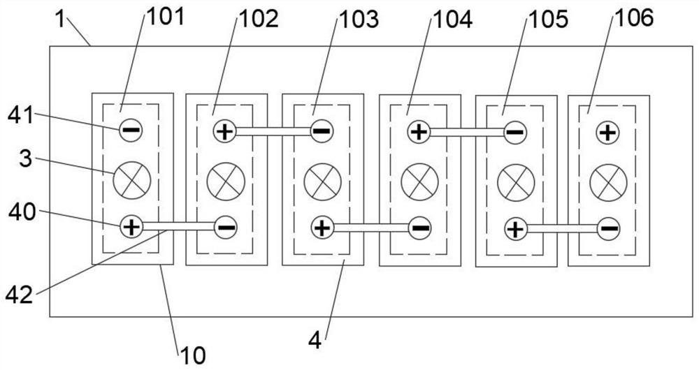
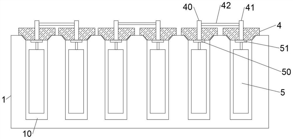
[0041] Aiming at the problems existing in the prior art, the embodiment of the present invention provides a combined battery pack, such as figure 1 It is a schematic top view structure diagram of the combined battery pack according to Embodiment 1 of the invention, figure 2 It is a schematic diagram of the front section structure of the combined battery pack according to the first embodiment of the present invention. refer to figure 1 with figure 2 , The combined battery pack of the present invention includes a plastic casing 1 , and at least two inner cavities 10 are arranged inside the plastic casing 1 . A battery cell 5 is installed inside each cavity 10 , and a cover plate 4 is sealed and fixed at the top opening of each cavity 10 . At least one positive pole 40 and one negative pole 41 are arranged on each cover plate 4, and each battery cell 5 is connected with one positive pole 40 and one negative pole 41, and the positive pole 40 on the cover plate 4 is connected ...
Embodiment 2
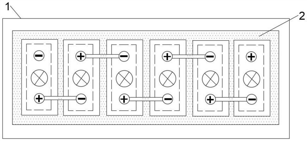
[0073] The invention provides a combined battery pack, such as Figure 5 as shown, Figure 5 It is a schematic plan view of the combined battery pack according to the second embodiment of the present invention; it includes a plastic casing 1, and six inner cavities 10 are arranged inside the plastic casing 1, and a battery cell 5 is installed inside each inner cavity 10 (Fig. not shown), the number of cover plates 4 is three, and each cover plate 4 covers two adjacent inner cavities 10, and each cover plate 4 is provided with two positive poles 40 and two negative poles 41. Each cover plate 4 is connected to its two battery cells. Each battery cell is connected to a positive pole 40 and a negative pole 41 , specifically, a positive pole 40 and a negative pole 41 are provided on the cover plate 4 directly above each inner cavity 10 . The connection between the battery cell (not shown in the figure) and the positive pole in the inner cavity 10, the connection method between th...
Embodiment 3
[0076] The invention provides a combined battery pack, such as Figure 7 as shown, Figure 7It is a schematic top view structure diagram of the combined battery pack according to the third embodiment of the present invention, which includes a plastic casing 1 and six inner cavities 10 are arranged inside the plastic casing 1 . The top openings of the six inner cavities 10 are jointly sealed and fixed with a cover plate 4, and six positive poles 40 and six negative poles 41 are arranged on the cover plate 4. The positive poles 40 on the cover plate 4 are connected in series with the adjacent negative poles 41 through the third connecting piece 42 .
[0077] Such as Figure 8 as shown, Figure 8 It is a schematic diagram of the front section structure of the combined battery pack according to Embodiment 3 of the present invention; a battery cell 5 is installed inside each cavity 10, and each battery cell 5 is connected to a positive pole 40 and a negative pole 41 Specificall...
PUM
 Abstract
Description
Claims
Application Information
 - R&D
- Intellectual Property
- Life Sciences
- Materials
- Tech Scout
- Unparalleled Data Quality
- Higher Quality Content
- 60% Fewer Hallucinations
Browse by: Latest US Patents, China's latest patents, Technical Efficacy Thesaurus, Application Domain, Technology Topic, Popular Technical Reports.
© 2025 PatSnap. All rights reserved.Legal|Privacy policy|Modern Slavery Act Transparency Statement|Sitemap|About US| Contact US: help@patsnap.com


