
Lens switching device

A conversion device and lens installation technology, applied in installation, optics, instruments, etc., can solve the problems of loss and damage of lens accessories, frequent replacement of lenses with different optical performances in optical equipment, etc., to achieve integration, improve operational convenience, and facilitate operation Effect

Pending Publication Date: 2021-01-08
JIANGSU ZONP TECH
View PDF0 Cites 0 Cited by
  • Summary
  • Abstract
  • Description
  • Claims
  • Application Information

AI Technical Summary

Problems solved by technology

[0004] The invention solves the problem of frequent replacement of lenses with different optical performances in optical equipment, and installs the external lenses used as replacement accessories inside the optical equipment, which can avoid the risk of loss and damage of lens accessories, and when the optical performance needs to be changed, just push the lever to switch Lenses, effectively improving the convenience of operation

Method used


Image

  • Lens switching device
  • Lens switching device
  • Lens switching device

Examples


Embodiment

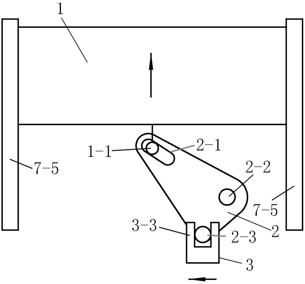
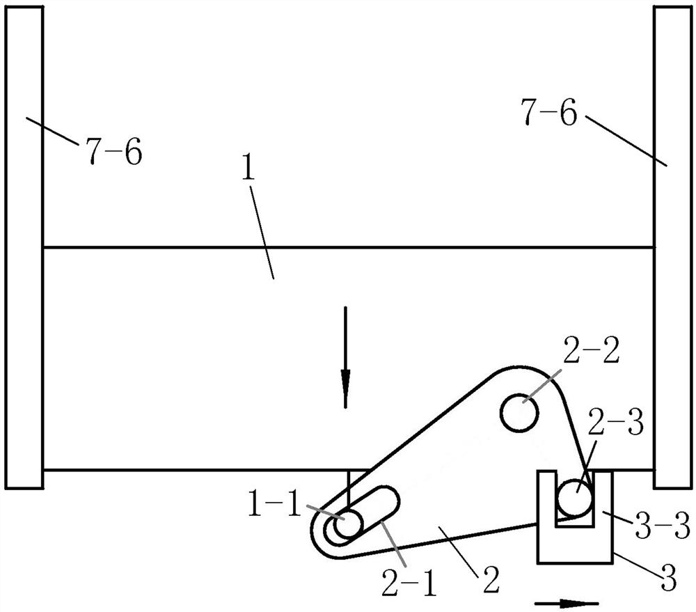
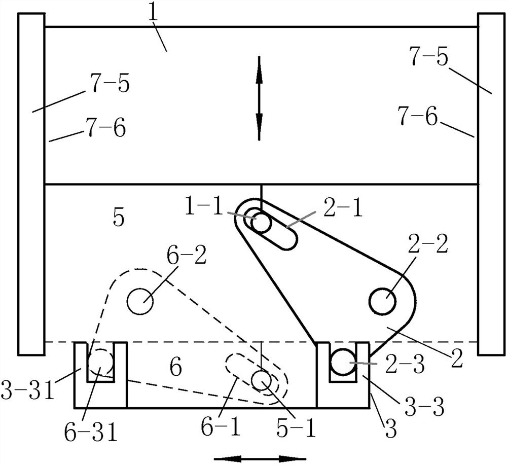
[0074] Such as Figure 1-8 As shown, the lens conversion device and method thereof include a front lens 1, a front rotating member 2, a shift lever 3, a front frame 4, a rear lens 5, a rear rotating member 6, and a rear frame 7; the outer frame 1-5 of the front lens 1 Embedded in the vertical chute 7-5, it can slide up and down. The lower end of the front lens 1 has the force pin 1-1 of the front lens; Slot 2-1, the front lens force pin 1-1 of the front lens 1 is stressed in the front rotating part chute 2-1 and can slide up and down with the rotation of the rotating part 2; the other end of the rotating part 2 has a front rotating part receiving force The power pin 2-3 is embedded in the dial groove 3-3 of the toggle lever 3. When the toggle lever 3 moves horizontally, the dial groove 3-3 pushes the force pin 2-3 of the front rotating part to make the rotating part 2 produce a certain angle. turn. The structures of the rear rotating part 6 and the rear eyeglass 5 are the sa...


PUM


Abstract

The invention relates to a lens switching device, in particular to a device which is arranged in optical equipment and can be used for quickly switching lenses. The lens switching device comprises a front lens, a front rotating piece, a poke rod, a front frame, a rear lens, a rear rotating piece and a rear frame, wherein the rear frame is mounted on the rear side of the front frame; the poke rod is mounted at the bottoms of the front frame and the rear frame; the front lens is mounted in a front lens sliding groove of the rear frame, and is connected with the poke rod through a front rotatingpiece; and the rear lens is installed in a rear lens sliding groove of the rear frame, and the rear lens is connected with the poke rod through a rear rotating piece. The lens switching device does not need to disassemble and replace the lenses, and can realize quick switching of the two lenses only by pushing the poke rod. The lens switching device solves the problem that lenses with different optical properties are frequently replaced by optical equipment, an external lens originally used as a replacement accessory is installed in the optical equipment, the risk that the lens accessory is lost and damaged is avoided, the lenses can be switched only by pushing the driving lever when the optical properties need to be changed, and the operation convenience is effectively improved.

Description

technical field [0001] The invention relates to a lens switching device, which is a device installed inside an optical device and can quickly switch lenses. Background technique [0002] In the optical field, some optical devices need to convert the wavelength of the output light during use. The conventional conversion method is to replace the filter with a different wavelength. The existing technology is to use lenses with different filter properties as equipment accessories. When the wavelength of light needs to be converted, the original filter lens (lens) is removed, and another filter lens (lens) with different wavelength parameters is installed. This method of replacing lenses (lenses) can solve the need to change the wavelength of light during use, and can meet the requirements of obtaining different wavelengths by being equipped with multiple lenses (lenses). However, in the occasions where two wavelengths of light need to be frequently switched, repeatedly loading ...

Claims


Application Information

Patent Timeline
Patent Type & Authority Applications(China)
IPC IPC(8): G02B7/00
CPCG02B7/006
Inventor 史建军
Owner JIANGSU ZONP TECH
Learn More