
Device for separating from each other a plurality of articles which are in contact with each other

a technology of articles and devices, applied in the field of paper, can solve the problems of invariability of devices, large disadvantages in operation, and partial overlap and consequent interconnection, and achieve the effect of efficient separation

Inactive Publication Date: 2002-08-06
FABIO PERINI SPA
View PDF10 Cites 13 Cited by
  • Summary
  • Abstract
  • Description
  • Claims
  • Application Information

AI Technical Summary

Benefits of technology

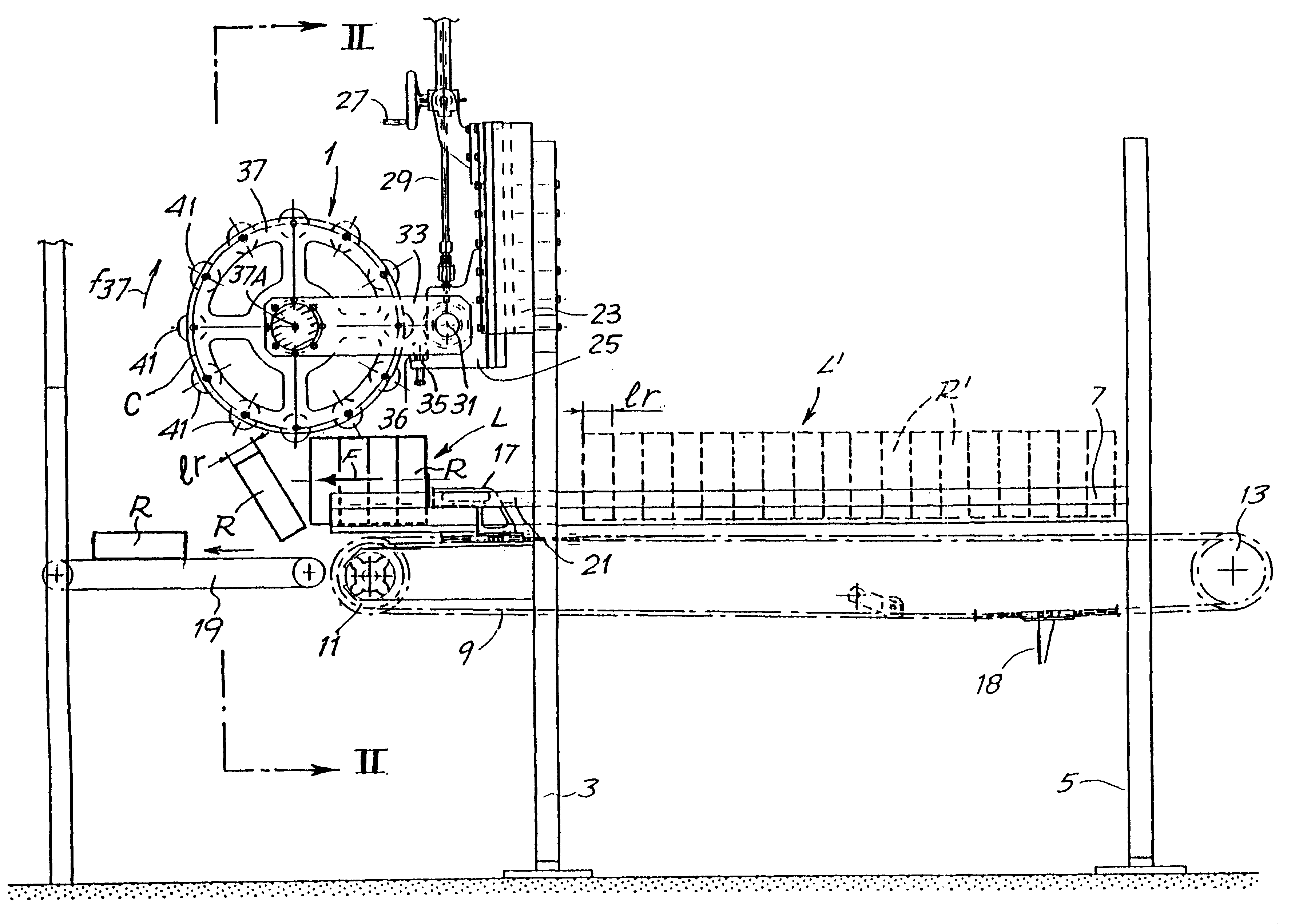
The object of the present invention is to provide a device which can be used to avoid the problems occurring at the packaging stage and which can be used to separate efficiently from each other the rolls produced by a rewinding and cutting machine or other similar machine.
More generally, the object of the present invention is to provide a device which can be used to separate efficiently from each other two or more similar articles which are adjacent to each other and may be partially adhering to each other.
In a particularly advantageous embodiment of the present invention, the rollers are supported so that they are free-running on said wheel. One result of this is to avoid the risk of damaging the articles on which the rollers act. This is particularly useful in the case of articles consisting of rolls of paper, for example tissue paper, such as rolls of toilet paper or similar products.
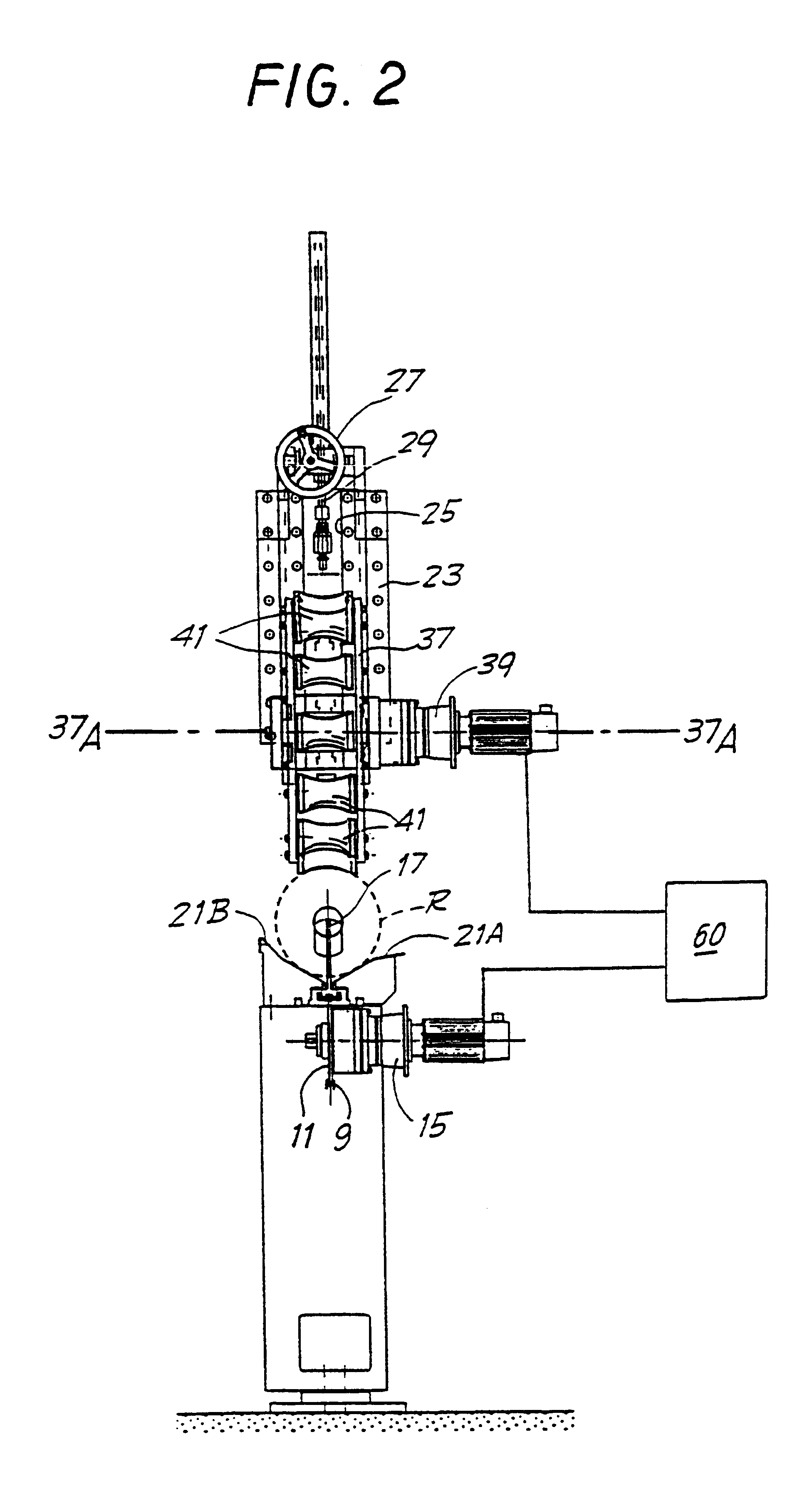
It is advantageous to arrange for the rotary movement of the rotatable member to be in phase with the movement of displacement of the individual articles along the advance path, in such a way that each article always receives a thrust at the same point. This may be achieved by means of a suitable mechanical drive and timing members included in it. Alternatively, and preferably, the timing may be provided electronically by a control unit which controls two motors, one for the rotation of the rotatable member and the other for the advance of the articles.
With the device according to the present invention, it is a simple matter to modify the direction and amount of the thrust exerted on the individual articles. The device can also be adapted easily to different sizes of the articles to be handled.

Problems solved by technology

One of the problems found in these machines is due to the fact that the bands of webmaterial tend to deviate in the area between the cutting and the winding, thus causing a partial overlapping and consequent interconnection of adjacent rolls caused by the partial penetration of the turns of one roil into those of the adjacent rolls.
This causes problems in the subsequent packaging stages, since interconnected rolls cannot be packaged.
Similar problems occur, for example, in machines called cutting machines for producing rolls of cardboard from strips of cardboard of greater length, or in machines for producing paper rolls for calculating machines or other office machines.
These devices are not versatile and have considerable disadvantages in operation.

Method used


Image

  • Device for separating from each other a plurality of articles which are in contact with each other
  • Device for separating from each other a plurality of articles which are in contact with each other
  • Device for separating from each other a plurality of articles which are in contact with each other

Examples


Embodiment Construction

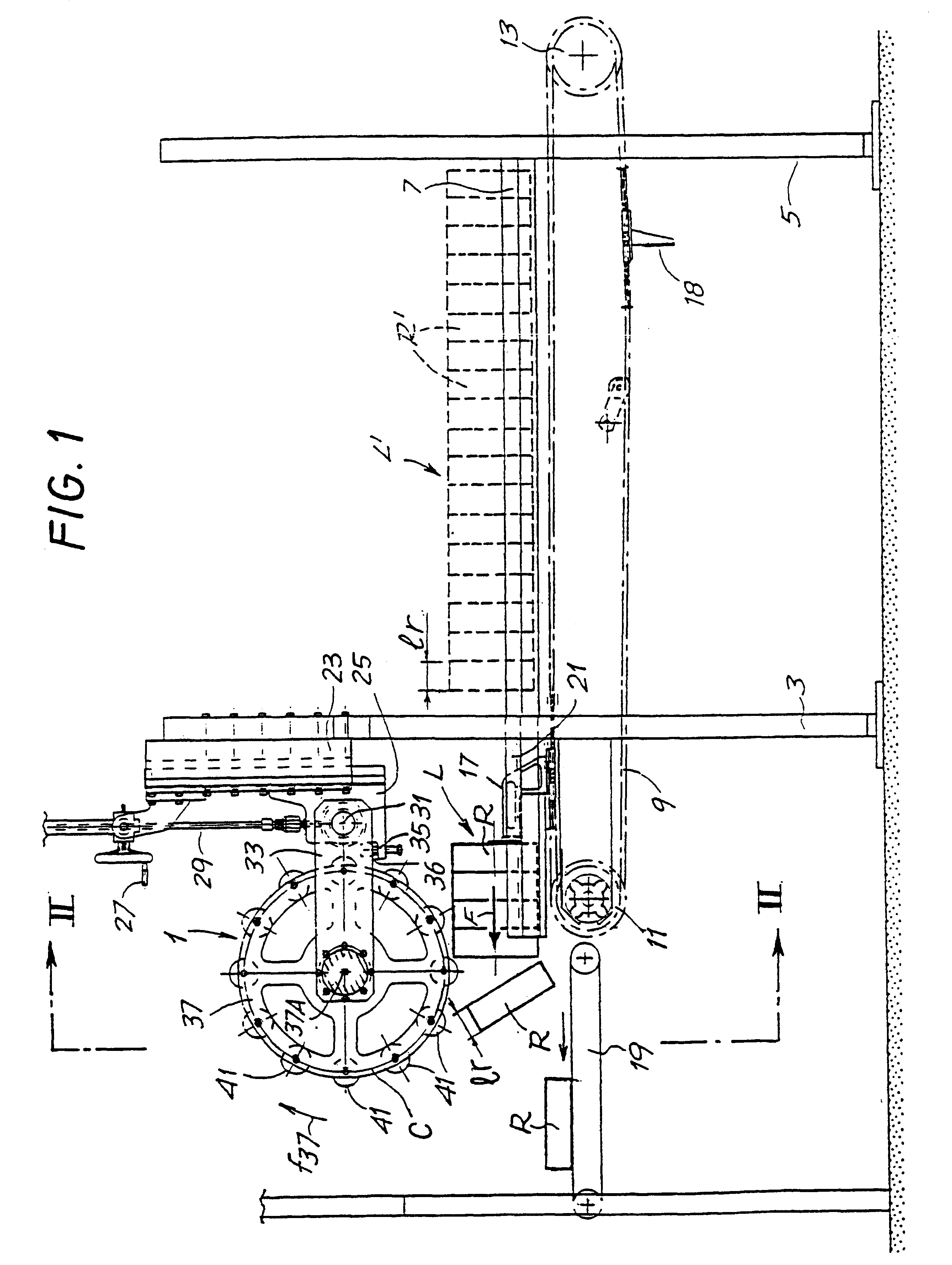
With initial reference to FIG. 1, the device indicated in a general way by 1 is linked to a side member 3 of a rewinding and cutting machine which is not shown and is of a type known per se. The second side member of the rewinding machine is indicated by 5. The letter L indicates a set of rolls R aligned with and adjacent to each other in the axial direction. They have been formed by the rewinding and cutting machine, and are now located on a discharge guide 7, which consists for example of a pair of sections forming a cradle supporting the rolls R. Under the guide 7 there is an endless flexible member 9, for example a chain, running around two wheels 11, 13, one of which is powered by an actuator, for example an electric motor 15, shown in FIG. 2. The flexible member 9 is provided with a pusher 17 which pushes the rolls R forward in the direction of the arrow F, to discharge them from the guide 7. When the discharge of a set L of rolls R is completed, the pusher 17 is made to withd...


PUM


Abstract

A description is given of a device for separating from each other a plurality of objects (R) which are adjacent to each other and are being fed in a direction of advance (F) along an advance path (21), comprising a member (37) which is rotatable about an axis of rotation (37A) and is positioned, with respect to the direction of advance, in such a way that it interferes with the articles (R) fed along said advance path. The peripheral velocity of said rotatable member at the point of contact between said member and said articles has a component substantially matching the direction of advance of the articles along said path.

Description

The present invention relates to a device which can be used to separate from each other a plurality of similar articles which are adjacent to each other.More particularly, the present invention relates to a device which is particularly suitable for separating from each other the rolls of a series or plurality of rolls of wound-up webmaterial, for example of the type produced by what is known as a rewinding and cutting machine, or rolls of cardboard produced by a cutting machine, rolls of printing paper, rolls of adhesive tape or other.PRIOR ARTIn the paper converting industry use is made of machines for producing rolls of paper material, for example rolls of toilet paper of relatively large diameter, usable in dispensers or feeders for communal areas, public premises or similar. These machines unwind the webmaterial from an initial reel having a large axial length, and cut the webmaterial by means of normally rotating cutters located along the path of the advance of the strip, to pr...

Claims


Application Information

Patent Timeline
Patent Type & Authority Patents(United States)
IPC IPC(8): B65G47/24B65H3/24B65G47/252B65H3/06B65G47/248B65H5/34
CPCB65G47/252B65H3/0646B65H3/24
Inventor BIAGIOTTI, GUGLIELMO
Owner FABIO PERINI SPA
Learn More