Compact container having discharge plate integrally injection molded by inserting sponge thereto

Pending Publication Date: 2021-09-02
PUMTECH KOREA
View PDF0 Cites 1 Cited by
  • Summary
  • Abstract
  • Description
  • Claims
  • Application Information

AI Technical Summary

Benefits of technology

The present patent is about a compact container for containing and discharging cosmetic material. The container has a discharge plate that is integrally injection molded onto a sponge, which is a structure that prevents the sponge from moving and ensures even distribution of the cosmetics. The sponge and discharge plate are securely joined without any gaps, which prevents the sponge from being swept away when rinsed in running water. The container also does not have any labyrinth-like diffusion space or small discharge holes, which reduces the amount of wasted cosmetic material. These features make the container more efficient and cost-effective than conventional containers.

Problems solved by technology

Solid-type base makeup cosmetics have excellent coverage, but may cause rash and poor adhesion when applied to skin.
Liquid-type base makeup cosmetics have excellent adhesion when applied to skin, but have poor durability.
However, the gel-type base makeup cosmetics are mainly applied after being put on the hand, but it is difficult to discharge a certain amount of cosmetics.
For this reason, cosmetics on the hand of a user may make his hand dirty, and bacteria may penetrate into the container from the hand, thereby contaminating the cosmetic material inside the container.
Although it is possible to consider how to put the cosmetics in a compact container and use it in the form of using a puff without getting it on hands, unlike solid-type base makeup cosmetics, volatile components of gel-type base makeup cosmetics may be volatilized, so that it is difficult to use cosmetics while the cosmetics are contained in the compact container without sealing.
However, according to the conventional compact container described above, since the outlet through which the cosmetics are discharged is formed only at a specific location, when the cosmetics are applied to the puff for use, the cosmetics are not evenly spread on the lower surface of the puff, but partially on the lower surface of the puff, so that it is difficult to spread evenly on the skin.
However, it is impossible to prevent the mixing cushion from moving up and down due to the pressure of the cosmetic material discharged through the discharge unit.
Accordingly, it is difficult to disperse the cosmetics evenly on the mixing cushion because the mixing cushion is lifted up by the cosmetics and a space is created between the mixing cushion and the discharge plate so that the discharge cosmetics are discharged while being gathered at one side in the space.
In addition, since the mixing cushion is not bonded to the discharge plate, there is a risk that the mixing cushion may be swept away by running water when the mesh is removed and washed with running water.
To prevent this, it was difficult to cleanly wash the mixing cushion due to the mesh net covered when washing without taking off the mesh net.
In addition, because the discharge plate with several small discharge holes is combined on the distribution plate formed with a labyrinth-like diffusion space, even if it is washed while flowing water over the discharge plate, it is impossible to cleanly wash various gaps such as a diffusion space between the distribution plate and the discharge plate, so that cosmetic residues are decayed or dried up, thereby causing skin troubles or preventing the contents from being properly discharged.
In addition, the assembly process is complicated because the compact container is additionally equipped with a distribution plate and a mesh net.
In particular, when the mixing mesh net is bonded to the joining part of the ring-shaped fixture, the manufacturing cost may increase due to the addition of a manufacturing process such as ultrasonic bonding, high-frequency bonding, or thermal bonding.

Method used


Image

  • Compact container having discharge plate integrally injection molded by inserting sponge thereto
  • Compact container having discharge plate integrally injection molded by inserting sponge thereto
  • Compact container having discharge plate integrally injection molded by inserting sponge thereto

Examples


Embodiment Construction

[0036]Technical objects to be achieved by the present disclosure and embodiments of the present disclosure will be apparent through preferable embodiments to be described below. Hereinafter, a compact container having a discharge plate integrally injection molded by inserting a sponge thereto according to an embodiment of the present disclosure will be described with reference to accompanying drawings.

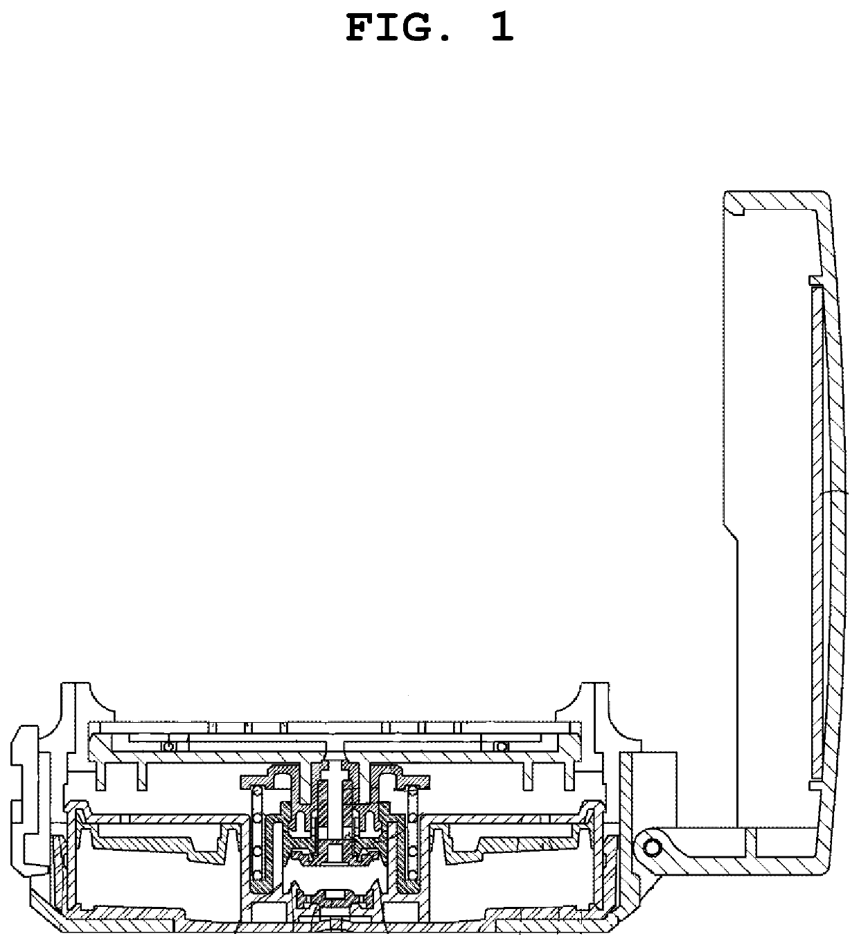
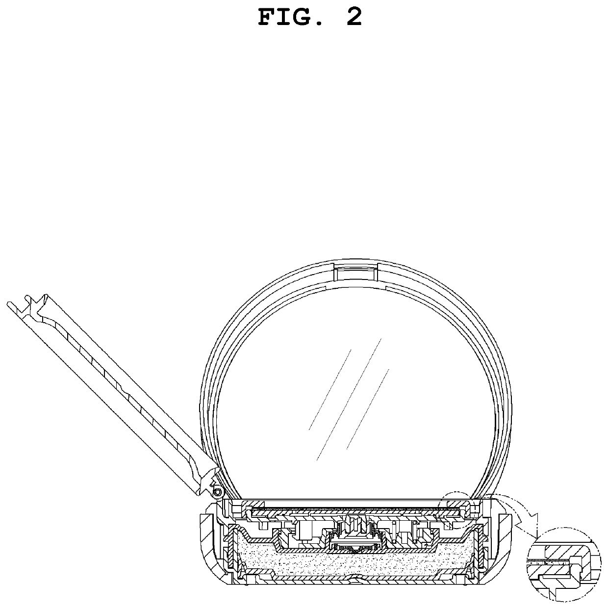
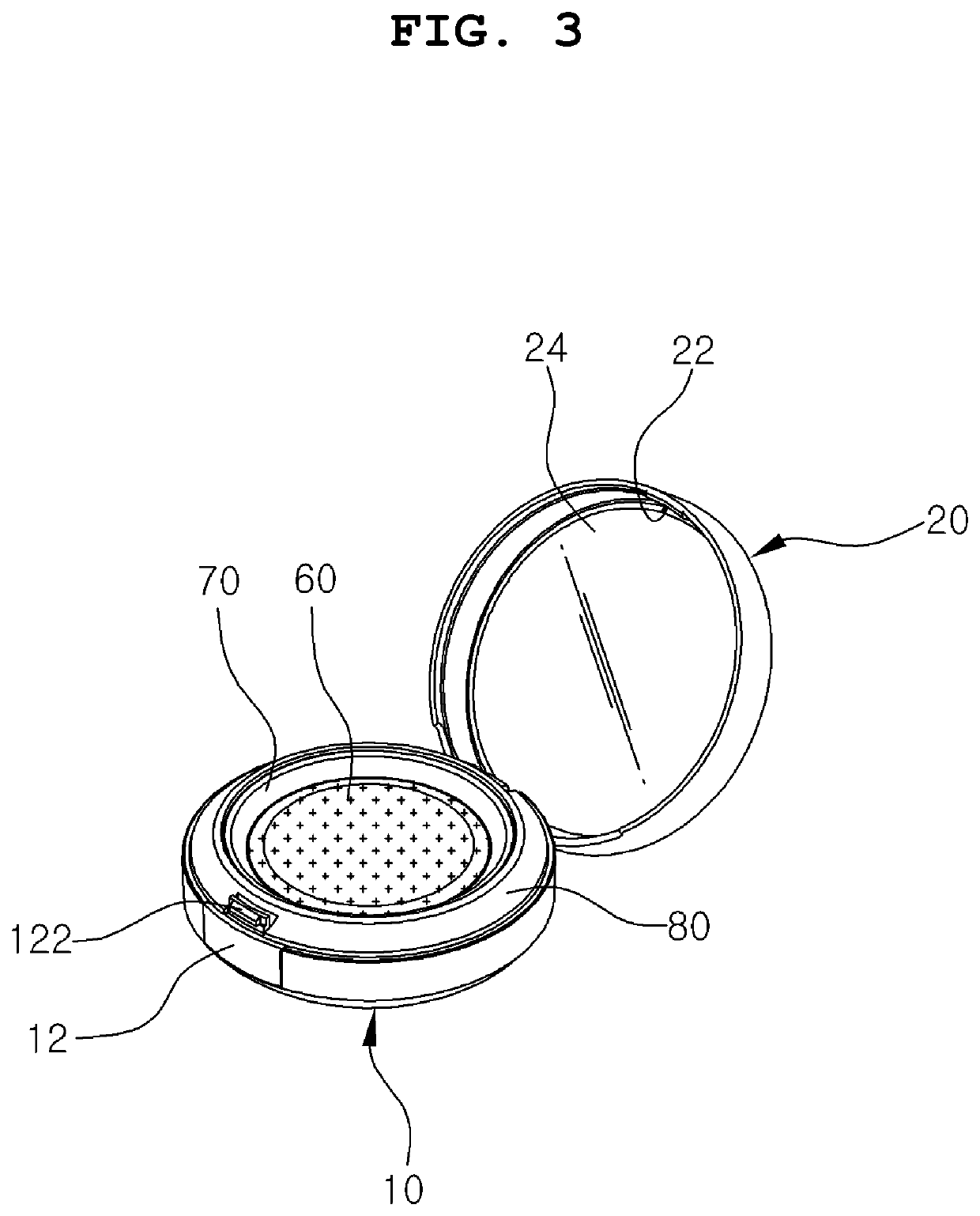
[0037]FIG. 3 is a perspective view illustrating a compact container according to an embodiment of the present disclosure. FIG. 4 is an exploded perspective view illustrating a compact container according to an embodiment of the present disclosure. FIG. 5 is a cross-sectional view illustrating a compact container according to an embodiment of the present disclosure.

[0038]A compact container having a discharge plate integrally injection molded by inserting a sponge thereto according to an embodiment of the present disclosure includes an inner container 30 for containing a cosmetic materi...


PUM

PropertyMeasurementUnit
Shapeaaaaaaaaaa

Abstract

A compact container that includes an inner container for accommodating a cosmetic material therein, a discharge unit for discharging the cosmetic material accommodated in the inner container, a discharge plate that is integrally injection molded by inserting a sponge thereto, a dish part in the shape of a small groove is formed at the center of the discharge plate so that the discharge plate and the sponge are spaced a certain distance apart from each other, and a joining part that is formed on the outside of the dish part so that the discharge plate and the sponge are joined without a gap by means of insert injection molding.

Description

BACKGROUND1. Technical Field[0001]One aspect of the present disclosure relates to a compact container which comprises an inner container for accommodating a cosmetic material therein and a discharge unit for discharging the cosmetic material accommodated in the inner container, and which has a discharge plate integrally injection molded by inserting a sponge thereto, the compact container enabling an even distribution of the discharged cosmetic material due to the sponge being in close contact with the discharge plate perfectly without moving, as the discharge plate and the sponge are integrally molded by means of insert injection molding by injection molding the discharge plate by inserting the sponge thereto. In addition, while the discharge plate and the sponge are integrally insert injection molded, a dish part in the shape of a small groove is formed at the center of the discharge plate so that the discharge plate and the sponge are spaced a certain distance apart from each oth...

Claims


Application Information

Patent Timeline
IPC IPC(8): A45D33/06
CPCA45D33/06A45D34/04A45D40/26B65D47/06A45D40/22A45D33/006B29C45/14795A45D2200/055A45D2200/056
Inventor LEE, DO HOON
Owner PUMTECH KOREA
Why Eureka
Try Eureka