
A blanking punching die

A blanking punching and die technology, applied in the direction of punching tools, manufacturing tools, peeling devices, etc., can solve the problems of unfavorable on-site 5S management, occupying large space and other problems, and achieve the effect of reducing the limitations of on-site space and die structure

Active Publication Date: 2019-12-31
ANHUI JIANGHUAI AUTOMOBILE GRP CORP LTD
View PDF5 Cites 0 Cited by
  • Summary
  • Abstract
  • Description
  • Claims
  • Application Information

AI Technical Summary

Problems solved by technology

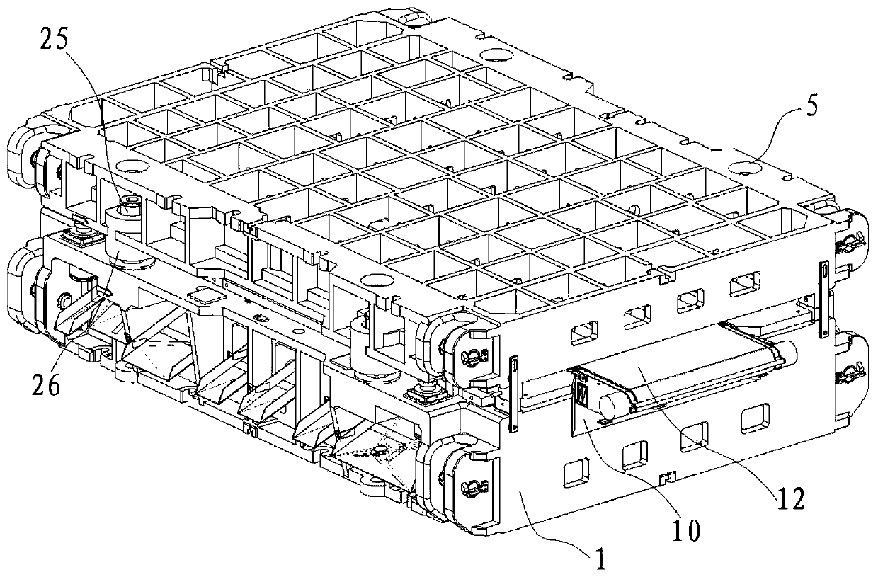
[0002] In order to improve material utilization and formability in stamping production, many covering parts are punched and drawn by blanking dies. With the popularization of automation lines, uncoiling and blanking lines have been widely used. In the production process, the material strips are generally After the separation of the upper and lower ends of the mold is completed, the material belt produced is transferred to the conveyor belt through the material guide frame, which is equivalent to designing a material guide belt and a conveyor belt in addition to the mold, which takes up a large space and is not conducive to on-site 5S management. There are also many restrictions on production space and mold structure

Method used


Image

  • A blanking punching die
  • A blanking punching die
  • A blanking punching die

Examples


Embodiment Construction

[0025] The embodiments described below by referring to the figures are exemplary only for explaining the present invention and should not be construed as limiting the present invention.

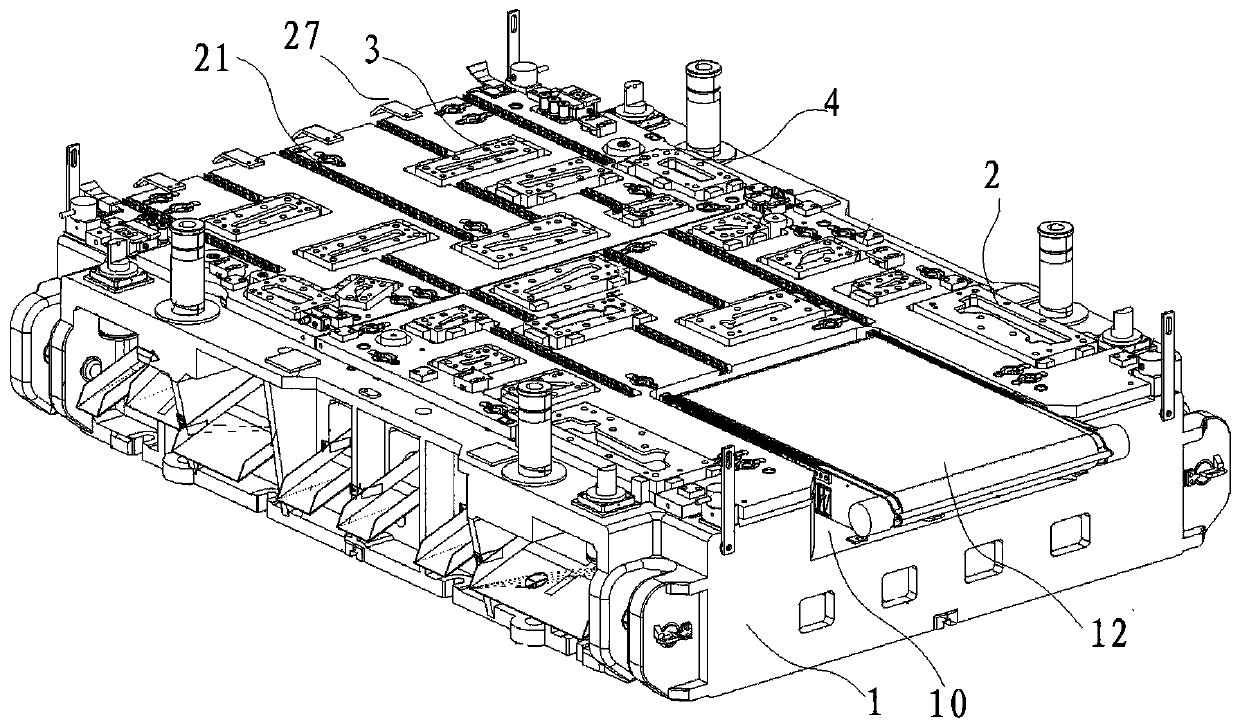
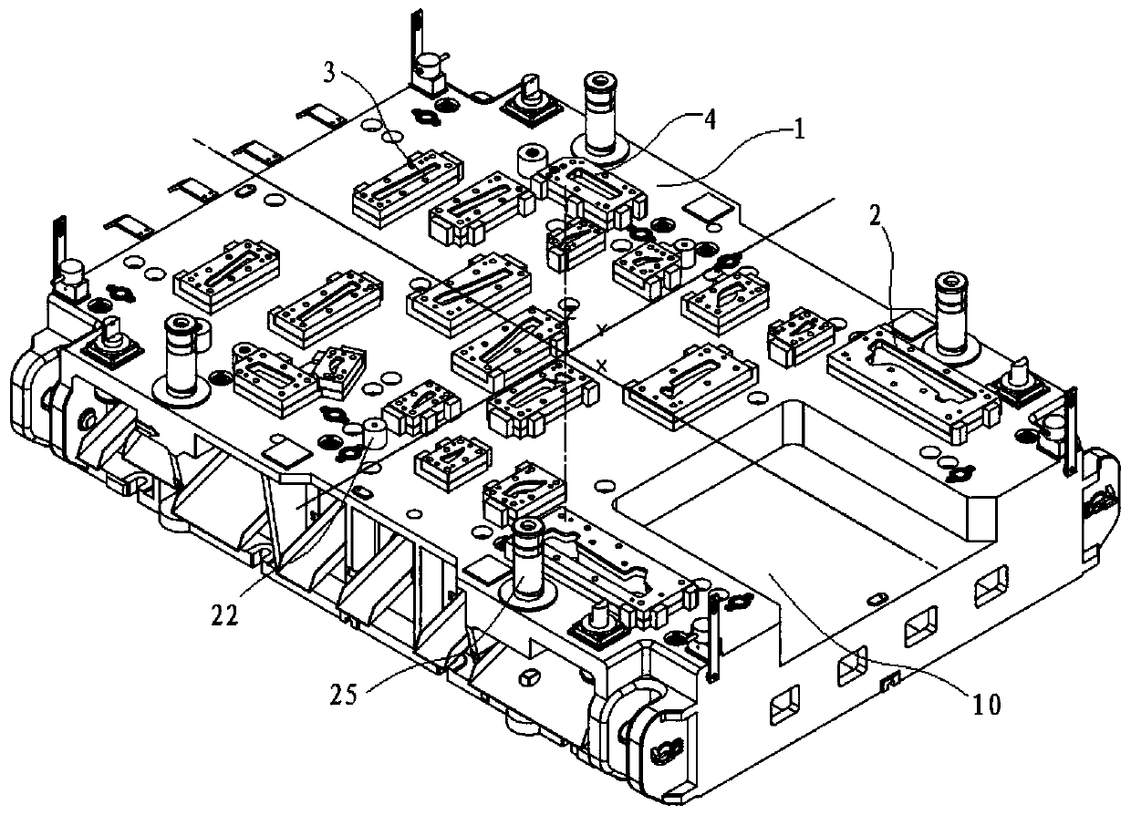
[0026] Such as Figure 1 to Figure 7 As shown, the embodiment of the present invention provides a blanking punching die, comprising:

[0027] The lower mold base 1, the lower mold base 1 is provided with a transmission assembly and a lower insert assembly, and the lower insert assembly includes more than two slitting die inserts 2, and more than two slitting die inserts Blocks 2 are distributed on the periphery of the transmission assembly. In this embodiment, the lower insert assembly also includes a punching die insert 3 for punching and a trimming die insert for trimming. Block 4, the shape, number and position of each insert in the lower insert assembly are flexibly configured according to actual production requirements, thereby improving the versatility of the mold and reducing producti...


PUM


Abstract

The invention discloses a blanking punching mold. The blanking punching mold includes a lower mold base and an upper mold base; a conveying assembly and a lower insert assembly are arranged on the lower mold base, the lower insert assembly comprises multiple slitting concave die inserts, and the slitting concave die inserts are distributed on the periphery of the conveying assembly; an upper insert assembly is arranged on the upper mold base and comprises multiple splitting convex die inserts, and the splitting convex die inserts are matched with the splitting concave die inserts one by one. Compared with the prior art, the blanking punching mold has the advantages that under the original width and length of the mold, a separation procedure is arranged at the last of the whole operation process of the mold, blanks are separated by splitting concave dies and splitting convex dies, the separated blanks are conveyed to an assigned position through the conveying assembly, and therefore output of the blanks without a material guiding belt is achieved. The conveying assembly is mounted in the mold, minimization of the space is achieved, and limitation caused by punching production to theon-site space and a mold structure is reduced.

Description

technical field [0001] The invention relates to the technical field of dies, in particular to a blanking and punching die. Background technique [0002] In order to improve material utilization and formability in stamping production, many covering parts are punched and drawn by blanking dies. With the popularization of automation lines, uncoiling and blanking lines have been widely used. In the production process, the material strips are generally After the separation of the loading and unloading ends of the mold is completed, the produced material belt is transferred to the conveyor belt through the material guide frame, which means that in addition to the mold, the material guide belt and the conveyor belt need to be designed, which takes up a lot of space and is not conducive to on-site 5S management. There are also many restrictions on the production space and mold structure. Contents of the invention [0003] The purpose of the present invention is to provide a blank...

Claims


Application Information

Patent Timeline
Patent Type & Authority Patents(China)
IPC IPC(8): B21D28/14B21D28/34B21D45/06
CPCB21D28/14B21D28/34B21D45/06
Inventor 何鹏申王肖英陈玉杰刘峰徐肖高双明李昂李杭井芊卢桥李月伟李辉
Owner ANHUI JIANGHUAI AUTOMOBILE GRP CORP LTD
Learn More