
Permanent magnet suitable for magnetic angle encoder

Active Publication Date: 2015-11-19
MULTIDIMENSION TECH CO LTD
View PDF7 Cites 1 Cited by
  • Summary
  • Abstract
  • Description
  • Claims
  • Application Information

AI Technical Summary

Benefits of technology

The present invention provides a suitable permanent magnet for a magnetic angle encoder, which can be installed within the counting wheel of an electronic water meter, while minimizing space. The cylindrical ring permanent magnets used in the present invention allow the distance from the end face of the permanent magnet to the detection plane within a specific area of the detection plane to vary over a wide range, so that the performance of the tunneling magnetoresistive sensor is less sensitive to the precise position of the sensor. The magnetic angle encoder of the present invention implemented as a water meter permits smaller size and better measurement accuracy.

Problems solved by technology

Unfortunately this technology suffers from digital errors, resulting from bubbles, light, dirt, leakage and other factors.
When tunneling magnetoresistive angle sensor encoder technology is applied to electronic water meter design there will be special performance and design requirements for the permanent magnets, which are difficult to meet with existing magnetic encoder technology due to the following issues:(1) Existing magnetic angle encoders mostly use Hall sensors to detect the magnetic field generated by the permanent magnet that is perpendicular to the surface of the sensor, and tunneling magnetoresistive sensors detect the magnetic field component parallel to the surface of the sensor, so existing permanent magnet designs are not compatible with the tunneling magnetoresistive sensors.(2) The existing permanent magnets used for magnetic angle encoders are usually a solid cylindrical design, and this is not compatible with the counting wheels used in typical water meters since the counting wheels are mounted on an axle that needs to pass through the center of each wheel and thus through the magnets.

Method used


Image

  • Permanent magnet suitable for magnetic angle encoder
  • Permanent magnet suitable for magnetic angle encoder
  • Permanent magnet suitable for magnetic angle encoder

Examples


example 1

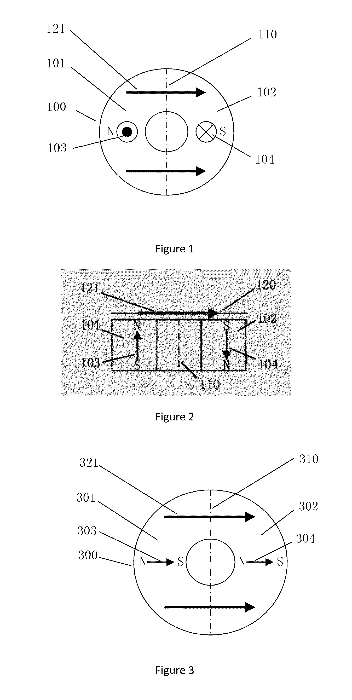
[0054]FIGS. 1 and 2 show schematic drawings of an embodiment of the permanent magnet 100 according of the present invention. The permanent magnet 100 has cylindrical ring geometry, and it is comprised of a permanent unit 101 and a permanent magnet unit 102, wherein permanent magnet unit 101 and permanent magnet unit 102 are symmetrically arranged about diametral cross-section 110. The magnetization directions 103 and 104 of permanent magnet units 101 and 102 are oriented in antiparallel directions along the axis. Preferably, the magnetization 103 of the permanent magnet unit 101 and the magnetization 104 of permanent magnet unit 102 have the same magnitude.

[0055]Those skilled in the art can design the permanent magnet 100 into any desired size. Preferably, the permanent magnet 100 is a cylindrical ring with inner diameter 1-100 mm, outer diameter of 3-200 mm, and has an axial length of 1-50 mm.

[0056]The detection plane 120 is located adjacent and parallel to the end face or permanen...

example 2

[0059]FIGS. 3 and 4 show schematic drawings of another embodiment of the permanent magnet 300 of the present invention. The permanent magnet 300 has cylindrical ring geometry, and it is comprised of a permanent unit 301 and a permanent magnet unit 302, wherein permanent magnet unit 301 and permanent magnet unit 302 are symmetrically arranged about diametral cross-section 310. The magnetization directions 303 and 304 of permanent magnet units 301 and 302 are oriented along a diameter in the same direction. Preferably, the magnetization 303 of the permanent magnet unit 301 and the magnetization 304 of permanent magnet unit 302 have the same magnitude.

[0060]Those skilled in the art can design the permanent magnet 300 into any desired size. Preferably, the permanent magnet 300 is a cylindrical ring with inner diameter 1-100 mm, outer diameter of 3-200 mm, and has an axial length of 1-50 mm.

[0061]The detection plane 320 is located in front of and parallel to the end face or permanent mag...

example 3

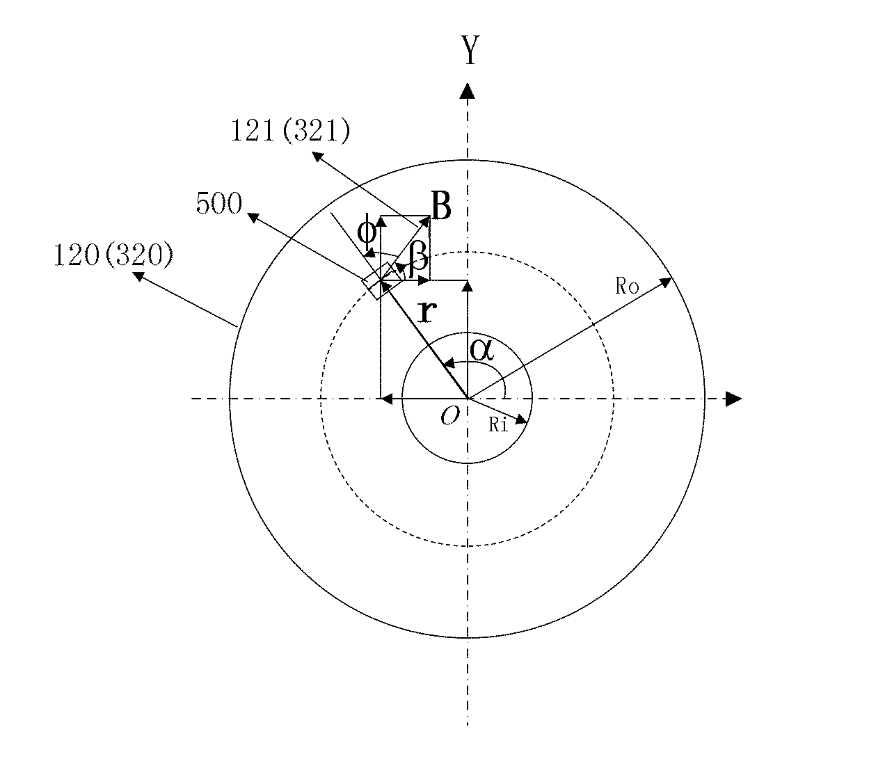
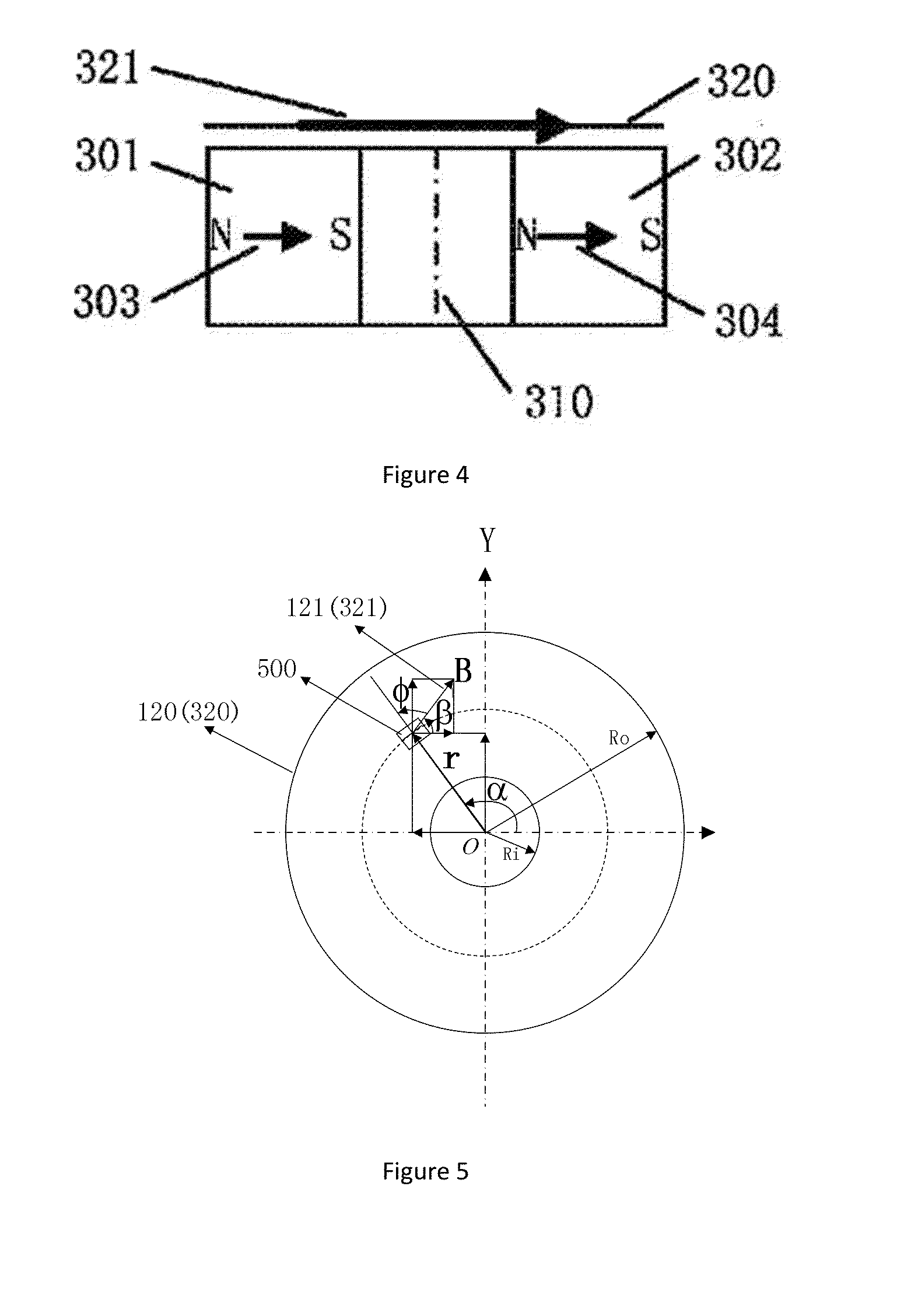
[0063]Example 3 of the present invention is a magnetic angle encoder that includes a rotating counting wheel that rotates about an axis, a permanent magnet embedded in the counting wheel, magnetic tunnel junction sensors, and digital processing circuitry. Tunneling magnetoresistance sensors are located in the detection plane adjacent to the permanent magnet, for sensing the magnetic field from the permanent magnet and outputting a signal. The tunneling magnetoresistive sensors are disposed at a certain radial distance from rotation axis within the detection plane of the permanent magnets, in this particular radial region of the detection plane of the rotating permanent magnet the magnetic field components have an angle φ that varies linearly with the rotation angle α of said permanent magnet. A digital processing circuit uses the output signal from the tunneling magnetoresistive sensors to calculate and output a code representative of the rotational angle of the permanent magnet.

[00...


PUM


Abstract

The present invention relates to a permanent magnet suitable for a magnetic angle encoder. The permanent magnet has an annular cylindrical structure and comprises a first permanent magnet unit and a second permanent magnet unit. The first permanent magnet unit and the second permanent magnet unit are geometrically symmetrical with respect to a diametral cross section. The magnetisation intensity of the first permanent magnet unit and the magnetisation intensity of the second permanent magnet unit are parallel to the axial direction of the annular cylinder and are in opposite directions, or the magnetisation intensity of the first permanent magnet unit and the magnetisation intensity of the second permanent magnet unit are perpendicular to the diametral cross section and are parallel to one another and in the same direction.

Description

TECHNICAL FIELD[0001]The present invention relates to a type of permanent magnet used for positional measurements, in particular, to a permanent magnet suitable for use in magnetic angle encoders, and instrumentation such as an electronic water meter that utilizes a magnetic angle encoder.BACKGROUND[0002]With the rapid development of sensor technology, the traditional mechanical flow meter, such as a residential water meter, has been gradually transitioning to a new electronic form. To this end, various sensor technologies have been employed, including optical encoder technology, which can be used to build an absolute angle encoder to enable the production of a direct read or absolute encoder water meter, which does not require an incremental encoder, to measure the amount of liquid flowing through the water meter. Unfortunately this technology suffers from digital errors, resulting from bubbles, light, dirt, leakage and other factors. Compared with optical encoder technology, magne...

Claims


Application Information

Patent Timeline
IPC IPC(8): H01F7/02H01F1/047H01F1/055H01F1/06
CPCH01F7/021H01F1/0551H01F1/047H01F1/06G01D5/145H01F7/0289
Inventor DEAK, JAMES GEZAZHOU, ZHIMIN
Owner MULTIDIMENSION TECH CO LTD
Learn More