This helps you quickly interpret patents by identifying the three key elements:
Problems solved by technology
Method used
Benefits of technology
Benefits of technology
The present invention aims to simplify the assembling process and improve the connecting strength between members of a protecting assembly for a battery module. The invention achieves this by using a limiting wall with inclinations in both the transverse and up-down directions, which can be easily slid into a groove and collaborate with a side wall to join the base and upper cover of the assembly. The inclinations provide stability and resistance to forces in various directions, ensuring a reliable connection that can withstand vibration without separating the base and upper cover. Overall, this invention simplifies the assembly process and improves the reliability of the protecting assembly for battery modules.
Problems solved by technology
However, the protection level of the existing protecting assembly is relatively low, and the connecting strength between the members of the protecting assembly is lower, so when the battery module is subjected to vibration, the protecting assembly is prone to failure.
Method used
Image
Click on the blue label to locate the original text in one second.
Reading with bidirectional positioning of images and text.
Examples
first embodiment
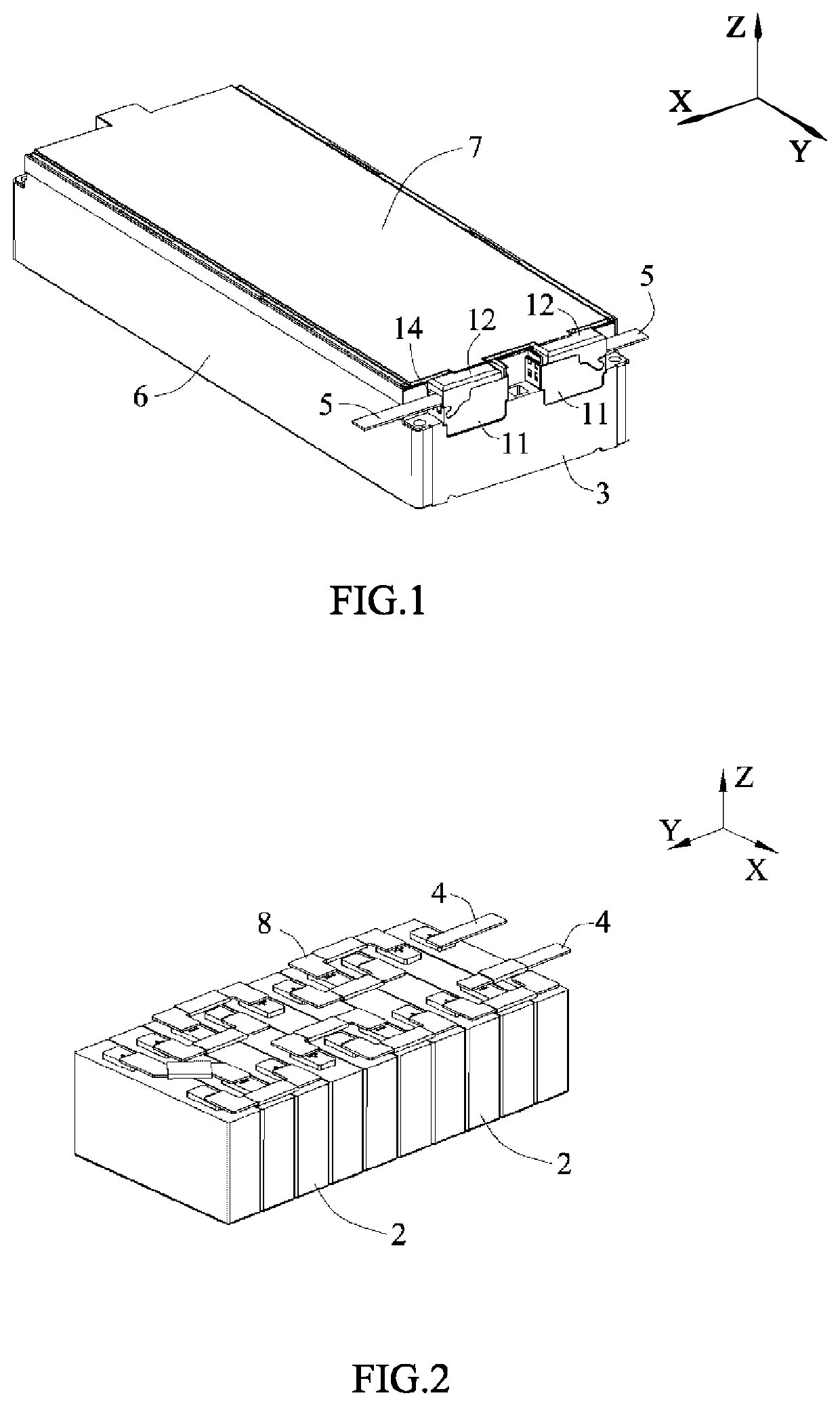
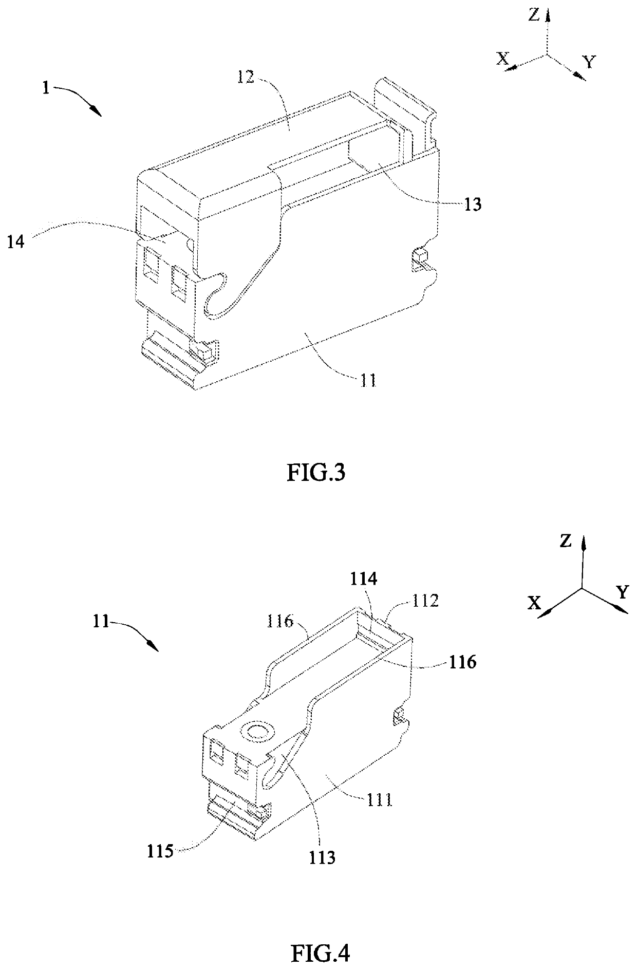
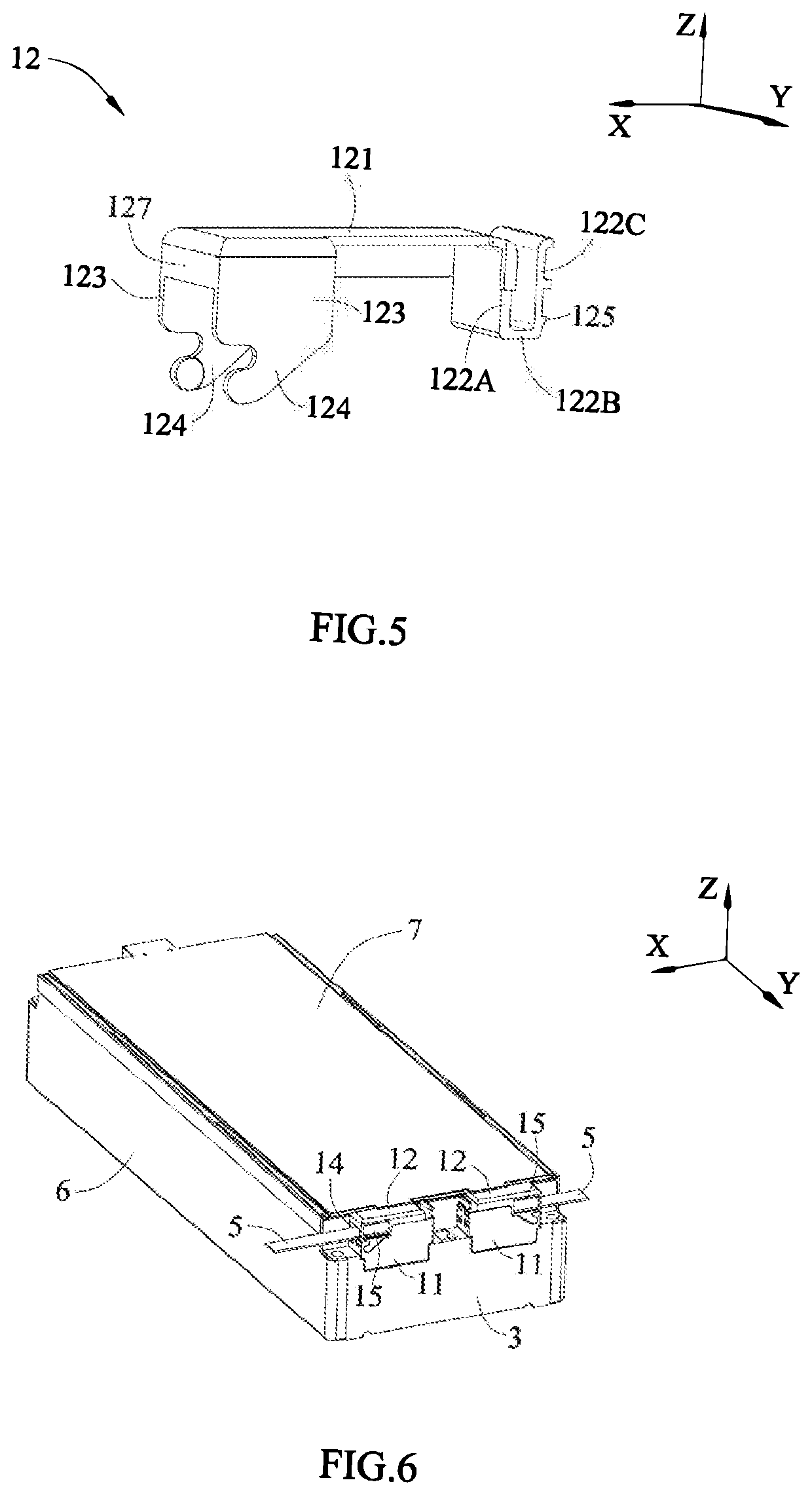
[0063]FIGS. 1-5 are schematic views of a battery module of the present disclosure.
[0064]Referring to FIG. 1 and FIG. 2, the battery module comprises a protecting assembly 1, a battery 2, an end plate 3, an outputting electrode piece 4, a connecting plate 6, a covering plate 7 and a connecting piece 8.
[0065]The battery 2 may be a prismatic lithium-ion battery, and have two electrode terminals protruded from the top thereof, that is a positive electrode terminal and a negative electrode terminal. The battery 2 is provided as plurality in number and the batteries 2 are sequentially arranged in a longitudinal direction Y. The end plate 3 is provided as two in number and the two end plates 3 are respectively provided to two ends of the batteries 2 in the longitudinal direction Y, the connecting plate 6 is provided as two in number and the two connecting plates 6 are respectively provided to two sides of the batteries 2 in a transverse direction X, the end plates 3 and the connecting plat...
third embodiment
[0087]The protecting assembly 1 of the third embodiment can have a structure as shown in FIG. 9. The ribs 126 are provided in the second opening 14 and the third opening 15. The strength of the ribs 126 is small, so the ribs 126 can be easily removed from the upper cover 12.
[0088]When two battery modules are arranged in the transverse direction X, the busbar 5 needs to extend into the receiving cavity via the second opening 14; at this time, based on the protecting assembly 1 in FIG. 9, it only needs to remove the ribs 126 in the second opening 14.
[0089]Compared to the second embodiment, the ribs 126 of the third embodiment can promote the closed performance of the receiving cavity of the protecting assembly 1, and improve the insulating function and the protecting function of the protecting assembly 1.
[0090]FIG. 8 is a schematic view of a fourth embodiment of the battery module of the present disclosure. Compared to the second embodiment, the upper cover 12 of the fourth embodiment...
fourth embodiment
[0091]The protecting assembly 1 of the fourth embodiment can have a structure as shown in FIG. 9. The ribs 126 are provided in the second opening 14 and the third opening 15. The strength of the ribs 126 is small, so the ribs 126 can be easily removed from the upper cover 12.
[0092]When two battery modules are arranged in the longitudinal direction Y, the busbar 5 needs to extend into the receiving cavity via the third opening 15; at this time, based on the protecting assembly 1 in FIG. 9, it only needs to remove the ribs 126 in the third opening 15.
[0093]Compared to the second embodiment, the ribs 126 of the fourth embodiment can promote the closed performance of the receiving cavity of the protecting assembly 1, and improve the insulating function and the protecting function of the protecting assembly 1.
PUM
Abstract
The present disclosure provides a battery module and a protecting assembly thereof. The protecting assembly comprises a base and an upper cover. The base is fixed to an end plate, a receiving cavity is formed between the upper cover and the base. An outputting electrode piece extends into the receiving cavity. The base comprises a basic body and a first side plate, the first side plate extends from the basic body, the basic body are provided with first grooves. The upper cover comprises a top wall, a first side wall extending downwardly from the top wall, a second side wall extending downwardly from the top wall and a limiting wall extending downwardly from the second side wall and inclined. The limiting wall is inserted into the first groove, the first side wall latches with the first side plate.
Description
CROSS-REFERENCE TO RELATED APPLICATIONS[0001]The present application claims priority to Chinese patent application No. CN201821680852.X, filed on Oct. 17, 2018, which is incorporated herein by reference in its entirety.FIELD OF THE PRESENT DISCLOSURE[0002]The present disclosure relates to the field of battery, and particularly relates to a battery module and a protecting assembly thereof.BACKGROUND OF THE PRESENT DISCLOSURE[0003]Electric current of batteries of a battery module is generally output via an outputting electrode piece; in order to protect the outputting electrode piece, the battery module is generally provided with a protecting assembly, the protecting assembly can realize the fixation and the insulation of the outputting electrode piece. However, the protection level of the existing protecting assembly is relatively low, and the connecting strength between the members of the protecting assembly is lower, so when the battery module is subjected to vibration, the protect...
Claims
Application Information
Patent Timeline
Application Date:The date an application was filed.
Publication Date:The date a patent or application was officially published.
First Publication Date:The earliest publication date of a patent with the same application number.
Issue Date:Publication date of the patent grant document.
PCT Entry Date:The Entry date of PCT National Phase.
Estimated Expiry Date:The statutory expiry date of a patent right according to the Patent Law, and it is the longest term of protection that the patent right can achieve without the termination of the patent right due to other reasons(Term extension factor has been taken into account ).
Invalid Date:Actual expiry date is based on effective date or publication date of legal transaction data of invalid patent.

