
Methods and arrangements to model an asynchronous interface

a technology of asynchronous interface and model, applied in the field of clock circuits, can solve the problems of circuit failure, skew/jitter logic is employed to model asynchronous, and skew/jitter logic cannot be used for elastic interfaces or other semi-static interfaces,

Inactive Publication Date: 2007-05-03
IBM CORP
View PDF13 Cites 38 Cited by
  • Summary
  • Abstract
  • Description
  • Claims
  • Application Information

AI Technical Summary

Benefits of technology

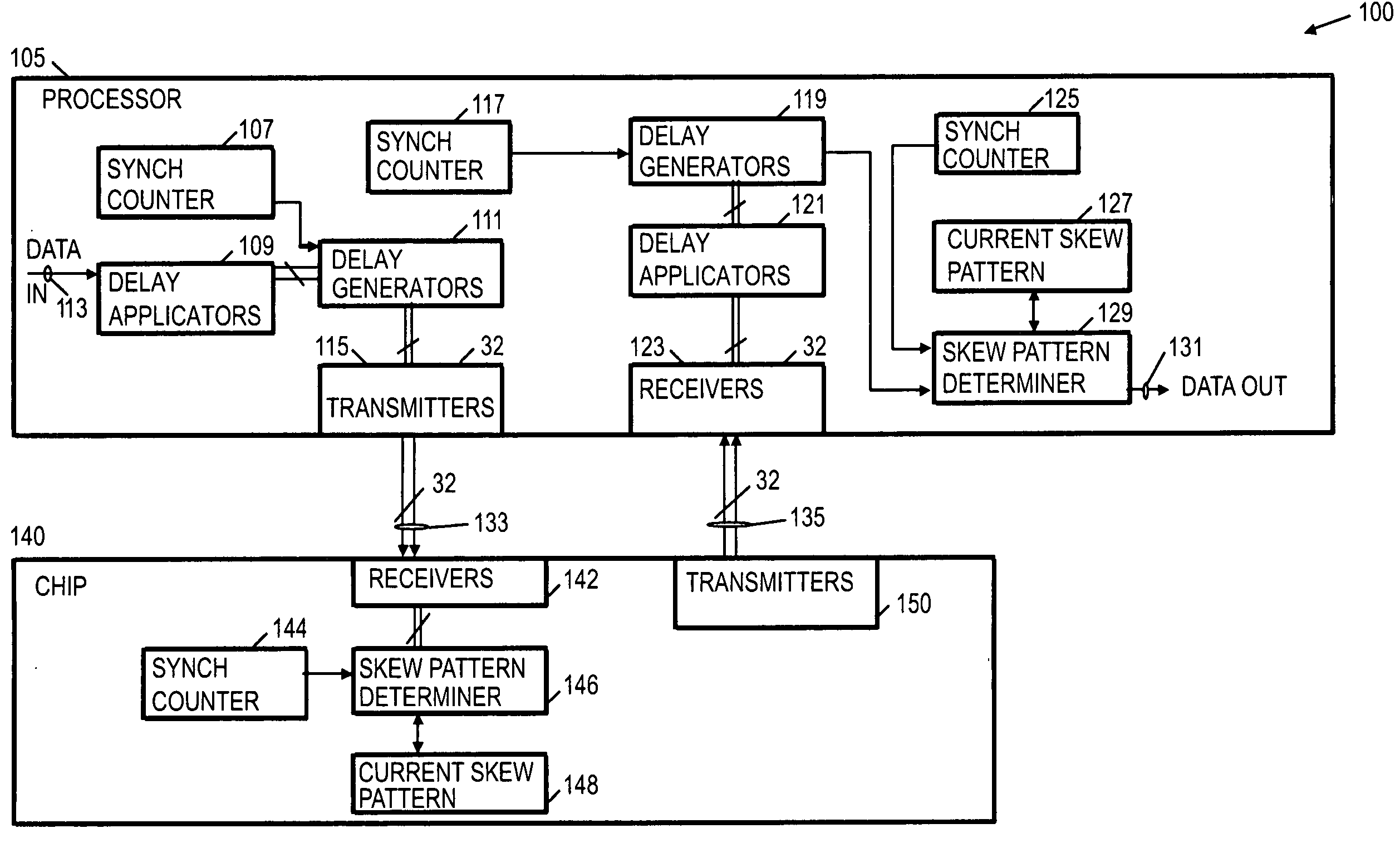
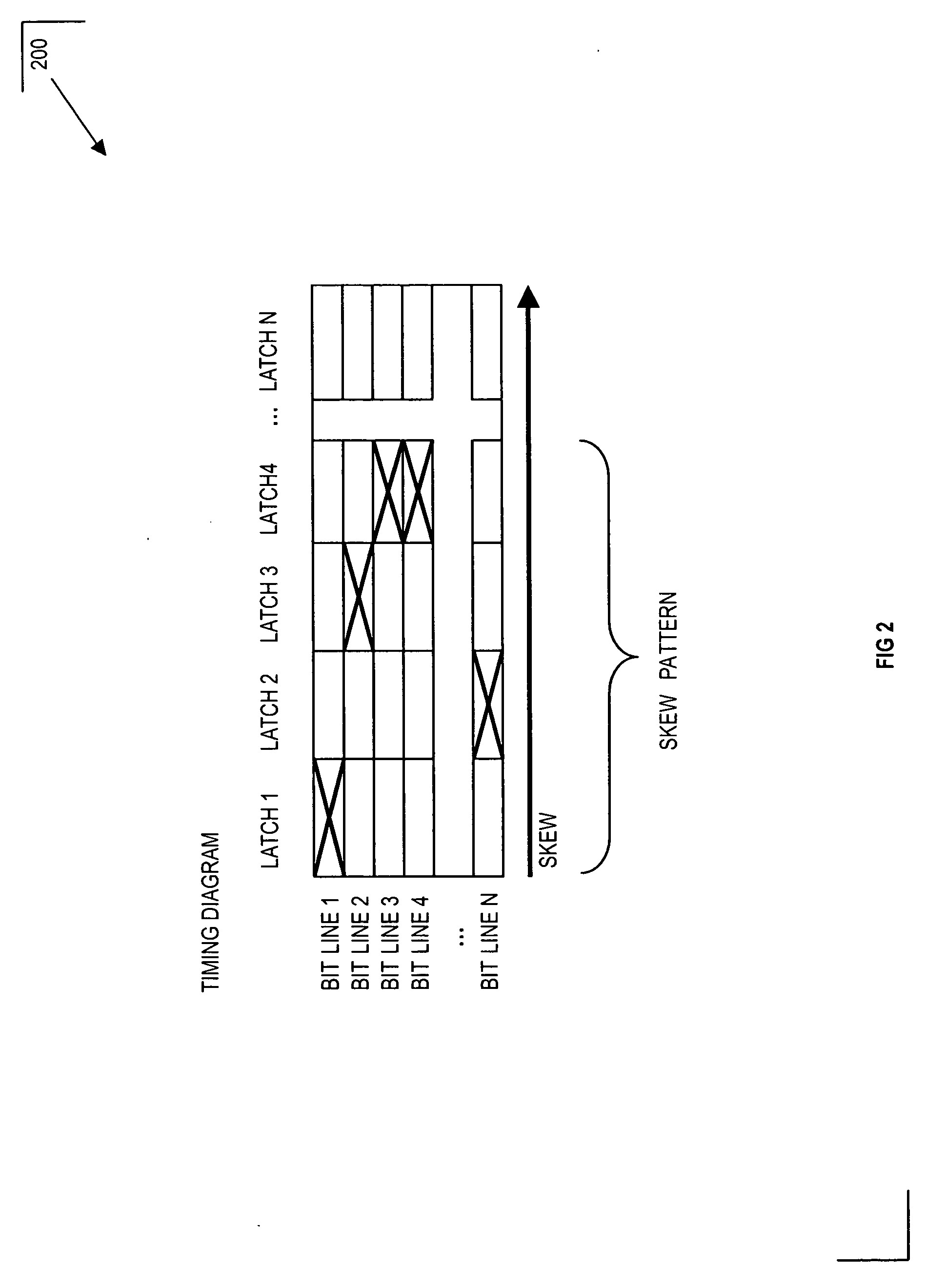
The patent text describes methods and arrangements to model the behavior of an asynchronous interface. This involves generating patterns of skews for a number of bit lines and applying them to bits associated with the lines during a time interval. A second pattern of skews is then applied to subsequent bits after the time interval. The technical effect of this invention is the ability to accurately model the behavior of asynchronous interfaces, which can aid in the design and development of electronic devices.

Problems solved by technology

Otherwise, the circuit will not function properly.
The problem with current circuit simulators from the perspective of the elastic interface is that skew / jitter logic is employed to model asynchronous behavior.
So skew / jitter logic cannot be used for elastic interfaces or other semi-static interfaces that require that the skew / jitter imposed remains static for a period of time.
The static skew pattern simulates one skew pattern of the elastic interface, however, this solution fails to simulate asynchronous behavior of the elastic interface at the expiration of the synchronous time interval, which is a potentially problematic aspect of the circuit operation.

Method used


Image

  • Methods and arrangements to model an asynchronous interface
  • Methods and arrangements to model an asynchronous interface
  • Methods and arrangements to model an asynchronous interface

Examples


Embodiment Construction

[0017] The following is a detailed description of embodiments of the invention depicted in the accompanying drawings. The embodiments are in such detail as to clearly communicate the invention. However, the amount of detail offered is not intended to limit the anticipated variations of embodiments, but on the contrary, the intention is to cover all modifications, equivalents, and alternatives falling within the spirit and scope of the present invention as defined by the appended claims. The detailed descriptions below are designed to make such embodiments obvious to a person of ordinary skill in the art.

[0018] Generally speaking, methods and arrangements to model an asynchronous interface are contemplated. Embodiments include transformations, code, state machines or other logic to generate a skew pattern for a semi-static or time-constrained, asynchronous interface and employ the skew pattern in data transfers during a time interval in which the asynchronous interface. Embodiments ...


PUM


Abstract

Methods and arrangements to model an asynchronous interface are disclosed. Embodiments include transformations, code, state machines or other logic to generate a skew pattern for a semi-static or time-constrained, asynchronous interface and employ the skew pattern in data transfers during a time interval in which the asynchronous interface. Embodiments may then alter the skew pattern in at the expiration of the time interval. In many embodiments, changes to the skew pattern may be substantially non-deterministic. In other embodiments, changes to the skew pattern may follow a heuristic or other dynamic or pre-determined pattern.

Description

FIELD OF INVENTION [0001] The present invention is in the field of clock circuits. More particularly, the present invention relates to methods and arrangements to model behavior of an asynchronous interface. BACKGROUND [0002] The push for high speed computing has led to the development of high speed, time-constrained, asynchronous links such as IBM's self-timed interfaces (STIs). In fact, the STI has been implemented in IBM's largest servers for several generations, providing successively improved input-output (I / O) subsystem bandwidth capacities. Time-constrained, asynchronous links are asynchronous data interfaces that transmit data over parallel bit lines via independent clock signals that are substantially synchronized at times. In particular, time-constrained, asynchronous interfaces, sometimes referred to as elastic or semi-static interfaces, may guarantee synchronous behavior over a specified time interval to facilitate data transfers. [0003] For purposes of the data transfer...

Claims


Application Information

Patent Timeline
Patent Type & Authority Applications(United States)
IPC IPC(8): H04L12/26H04J3/06H04J1/16
CPCG06F13/4291
Inventor JA, YEENELSON, BRADLEY S.
Owner IBM CORP
Learn More