
Non-blocking cyclic AWG-based node architectures

Inactive Publication Date: 2007-05-03
LUCENT TECH INC
View PDF6 Cites 20 Cited by
  • Summary
  • Abstract
  • Description
  • Claims
  • Application Information

AI Technical Summary

Benefits of technology

[0008] The foregoing, together with other aspects of this invention, will become more ap

Problems solved by technology

Many optical communications network cross-connect architectures are inefficient.
Unfortunately, they exhibit poor scalability, exhibit internal blocking, and / or require tunable lasers with wavelength range beyond the input wavelengths.

Method used


Image

  • Non-blocking cyclic AWG-based node architectures
  • Non-blocking cyclic AWG-based node architectures
  • Non-blocking cyclic AWG-based node architectures

Examples


Embodiment Construction

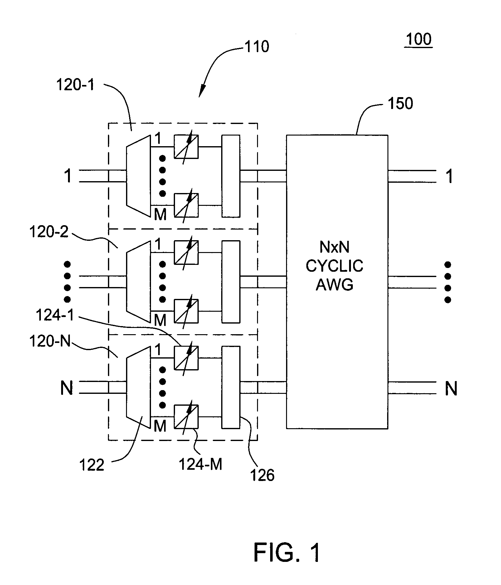
[0016] The invention will be primarily described within the context of non-blocking cyclic arrayed waveguide grating (AWG) node architecture; however, those skilled in the art and informed by the teachings herein will realize that the invention is also applicable to any apparatus and method that involves cross-connections of optical signals in a communications network.

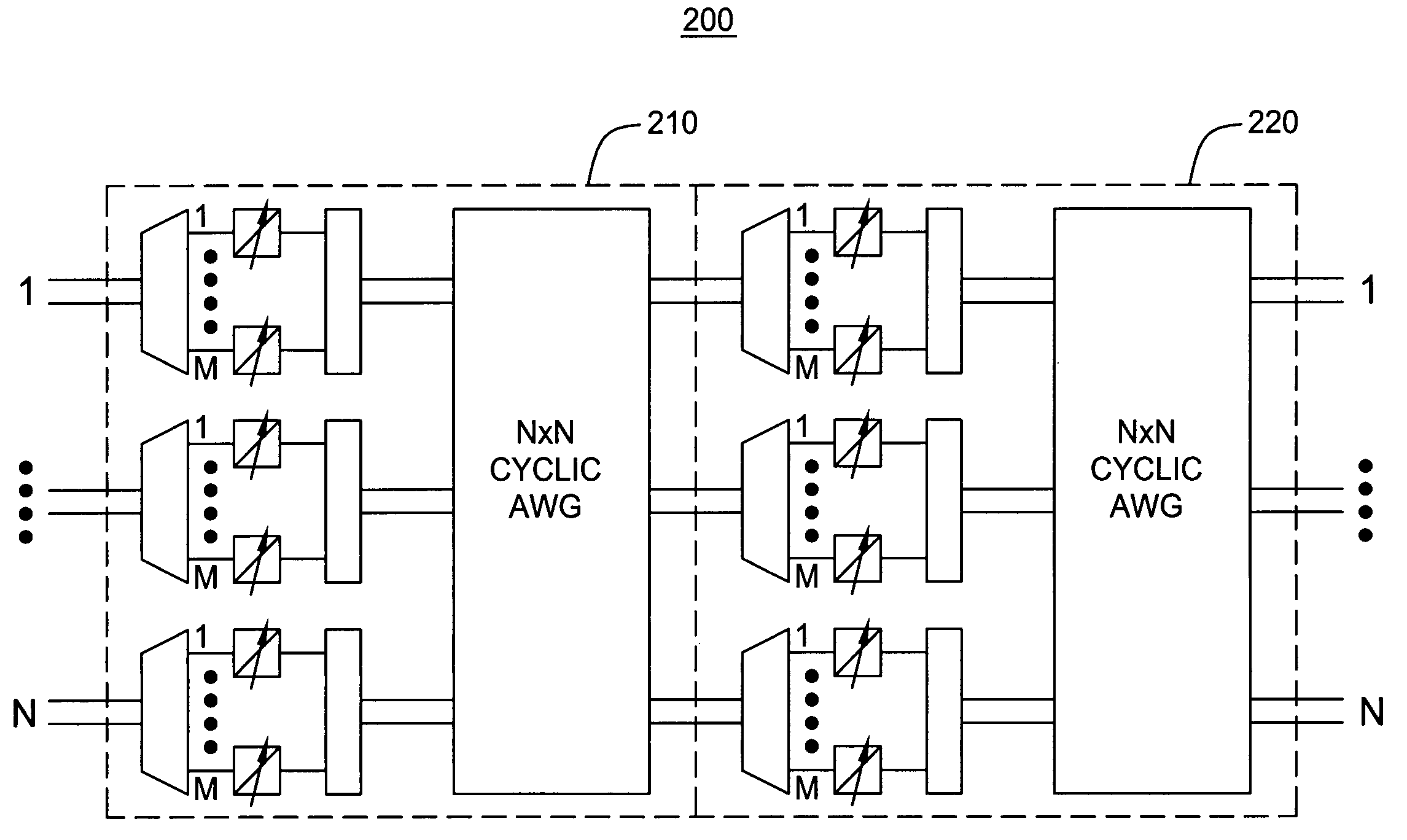
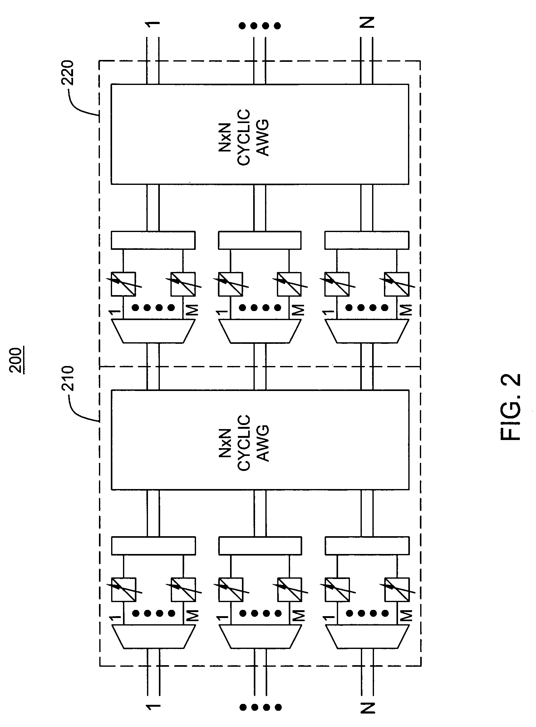
[0017]FIG. 1 depicts a block diagram of scalable optical switching architecture 100. The switching architecture 100 of FIG. 1 comprises a first stage 110 for pre-processing received optical signals and an N×N cyclic arrayed waveguide grating (AWG) 150 for cyclically switching the pre-processed optical signals. The switching architecture 100 comprises an N×N switching architecture in which information provided via any component wavelength or channel of any of N received Wavelength Division Multiplexed (WDM) input signals may be routed to any of N WDM output signals.

[0018] The first stage 110 comprises N tuner modules ...


PUM


Abstract

An optical switching architecture utilizing a multiple stage configuration of wavelength division multiplexed (WDM) component wavelength converters and cyclic arrayed waveguide grating (AWG) routers.

Description

FIELD OF THE INVENTION [0001] The invention is related to the field of optical telecommunications, and in particular, to optical switching architectures. BACKGROUND OF THE INVENTION [0002] Today's optical communications networks carry large amount of information over long distances. Many optical communications network cross-connect architectures are inefficient. Unfortunately, they exhibit poor scalability, exhibit internal blocking, and / or require tunable lasers with wavelength range beyond the input wavelengths. SUMMARY [0003] Various deficiencies of the prior art are addressed by the present invention of an optical switching architecture utilizing a multiple stage configuration of wavelength division multiplexed (WDM) component wavelength converters and cyclic arrayed waveguide grating (AWG) routers. [0004] In one embodiment, an optical switching apparatus comprises a first stage, for selectively adapting component channel wavelengths of N received wavelength division multiplexed...

Claims


Application Information

Patent Timeline
IPC IPC(8): G02B6/26
CPCG02B6/12021H04Q11/0005H04Q2011/0011H04Q2011/0016H04Q2011/0024H04Q2011/0032H04Q2011/0052H04Q2011/0075
Inventor JENNEN, JEAN GERARDUS LEONARDUS
Owner LUCENT TECH INC
Learn More