
Dry fiber optic cables and assemblies

a fiber optic cable and fiber optic technology, applied in the direction of optics, fibre mechanical structures, instruments, etc., can solve the problems of limited bandwidth, copper cables have drawbacks, and transmit a relatively limited amount of data with a reasonable cable diameter

Inactive Publication Date: 2007-05-03
BELDEN TECHNOLOGY INC +1
View PDF63 Cites 73 Cited by
  • Summary
  • Abstract
  • Description
  • Claims
  • Application Information

AI Technical Summary

Problems solved by technology

However, copper cables have drawbacks because they are large, heavy, and can only transmit a relatively limited amount of data with a reasonable cable diameter.
In other words, subscribers have a limited amount of available bandwidth due to the constraints of copper cables in the communication network.
But certain obstacles exist that make it challenging and / or expensive to route optical waveguides / optical cables closer to the subscriber.
However, it can be difficult to locate the correct fibers, and even when they are located, removing them from the cable without damaging the selected optical fibers or other optical fibers in the cable can be challenging.
Conducting the access process with conventional cables in less-than-ideal conditions in the field is time-consuming, expensive, and risks damaging the optical fibers of conventional cables.
Likewise, the access process is difficult in the factory with conventional cables.

Method used


Image

  • Dry fiber optic cables and assemblies
  • Dry fiber optic cables and assemblies
  • Dry fiber optic cables and assemblies

Examples


Embodiment Construction

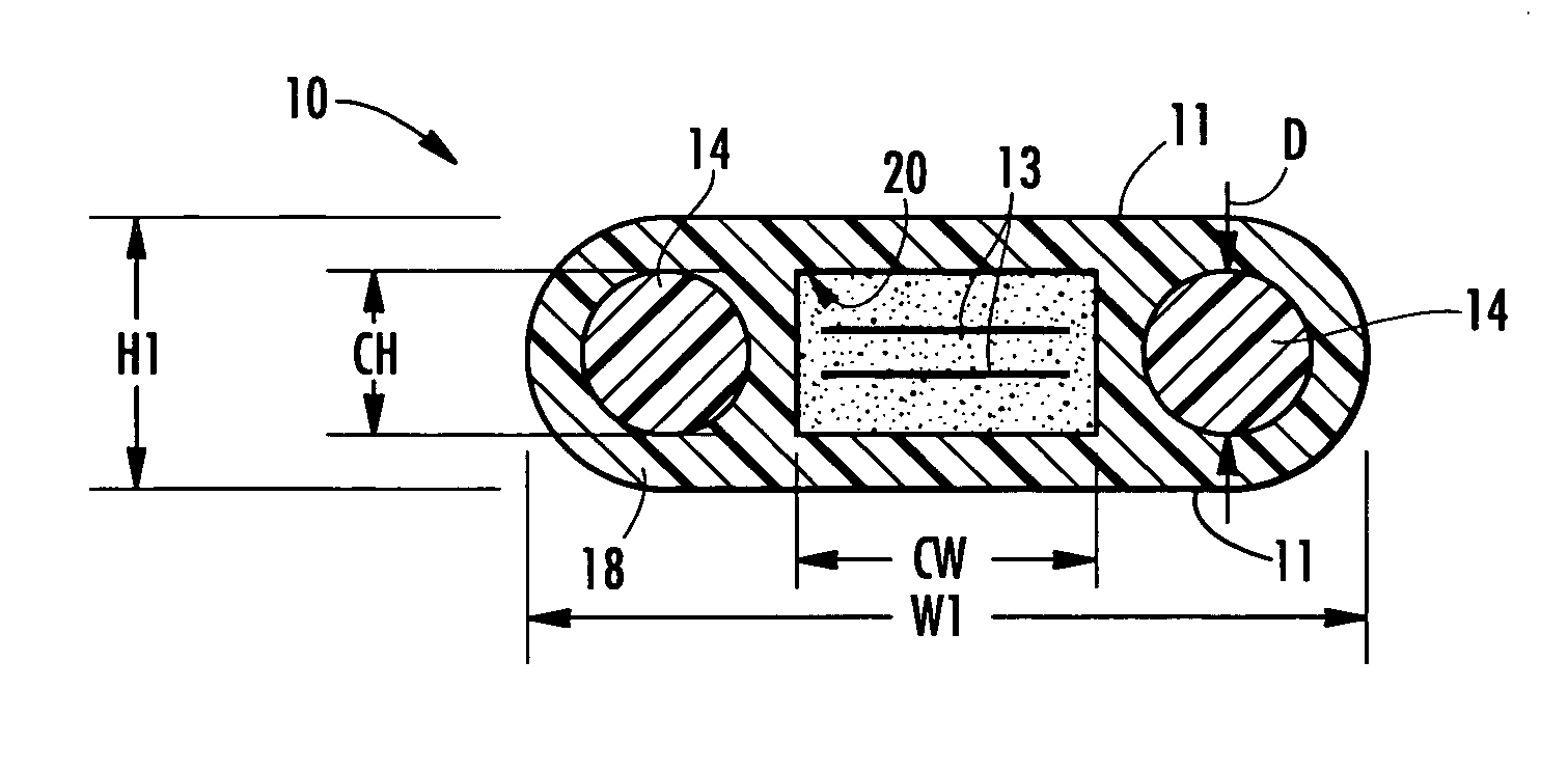
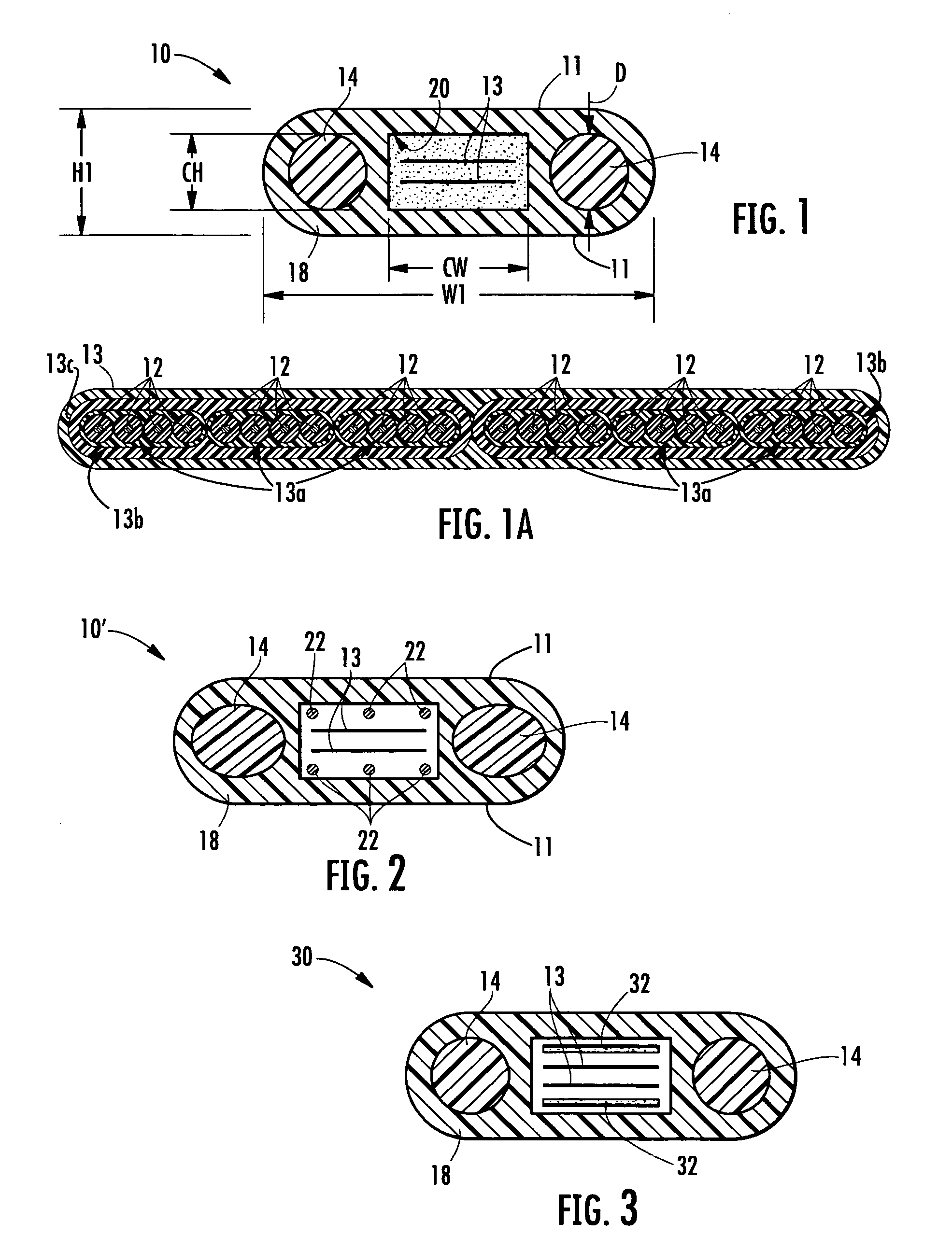
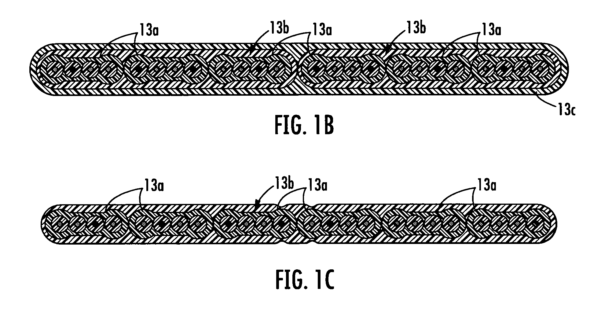
[0027] Reference will now be made in detail to exemplary embodiments of the invention, examples of which are described herein and shown in the accompanying drawings. Whenever practical, the same reference numerals are used throughout the drawings to refer to the same or similar parts or features. FIG. 1 depicts an exemplary fiber optic cable 10 (hereinafter cable 10) according to the present invention that can be configured for use as a drop cable, a distribution cable, or other suitable portions of an optical network. Generally speaking, a distribution cable will have a relatively high optical fiber count such twelve or more optical fibers for further distribution to the optical network. On the other hand, a drop cable will have a relatively low optical count such as up to four optical fibers for routing towards a subscriber or a business, but drop cables may include higher fiber counts. Cable 10 generally includes at least one optical fiber 12 disposed as a portion of an optical f...


PUM


Abstract

A fiber optic cable includes at least one optical fiber, at least one strength member, at least one dry insert, and a cable jacket. The cable jacket has a cavity with a generally rectangular cross-section with the at least one optical fiber and the at least one dry insert disposed therein. The at least one optical fiber has a predetermined level of coupling to the cable jacket that is provided by the at least one dry insert within the cavity of cable jacket. The predetermined level of coupling is about 0.1625 Newtons or more per optical fiber for a thirty meter length of fiber optic cable. Additionally, fiber optic cables of the present invention are also suitable as a portion of a cable assembly.

Description

RELATED APPLICATIONS [0001] This application is a Continuation-In-Part (CIP) of U.S. Ser. No. 11 / 193,516 filed on Jul. 29, 2005, which is a Continuation-In-Part (CIP) of U.S. Ser. No. 11 / 224,456 filed on Sep. 12, 2005, which is a Continuation application of U.S. Ser. No. 10 / 326,022 filed on Dec. 19, 2002 now U.S. Pat. No. 6,970,629, all of which are incorporated herein by reference.FIELD OF THE INVENTION [0002] The present invention relates generally to dry fiber optic cables and assemblies that are useful for routing optical fibers such as toward the subscriber. Specifically, the fiber optic cables and assemblies of the present invention are useful as feeder cables, distribution cables, drop cables, and / or other suitable cables / assemblies in an optical network. BACKGROUND OF THE INVENTION [0003] Communication networks are used to transport a variety of signals such as voice, video, data transmission, and the like. Traditional communication networks use copper wires in cables for tr...

Claims


Application Information

Patent Timeline
Patent Type & Authority Applications(United States)
IPC IPC(8): G02B6/44
CPCG02B6/02357G02B6/0281G02B6/0365G02B6/4403G02B6/4404G02B6/4433G02B6/4483G02B6/4494G02B6/443G02B6/4434G02B6/44384G02B6/4401G02B6/02395G02B6/4431G02B6/4429G02B6/2551G02B6/3851G02B6/3885G02B6/4473
Inventor BRINGUIER, ANNE G.GREENWOOD, JODY L.SEDDON, DAVID ALANTEMPLE, KENNETH D. JR.
Owner BELDEN TECHNOLOGY INC
Learn More