Saddle-shaped mitral valve annuloplasty prostheses with asymmetry, and related methods

a technology of annuloplasty and mitral valve, applied in the field of medical devices, can solve the problems of mitral valve incompetence, mitral valve regurgitation, and disruption of the natural coaptation of mitral leaflets and the natural distribution of mitral leaflets

Inactive Publication Date: 2007-05-03
ST JUDE MEDICAL LLC
View PDF14 Cites 51 Cited by
  • Summary
  • Abstract
  • Description
  • Claims
  • Application Information

AI Technical Summary

Benefits of technology

[0009] In accordance with the present invention, patient conditions like those described above are treated by applying an annuloplasty prosthesis (ring or C) that is shaped to push down the mitral valve annulus in the vicinity of the posterior commissure relative to other portions of the annulus. The pro

Problems solved by technology

Ischemic heart disease can cause a mitral valve to become incompetent.
In severe cases of left ventricle dilation, the tethering of the chordae prevents the leaflets from coming together or coapting

Method used


Image

  • Saddle-shaped mitral valve annuloplasty prostheses with asymmetry, and related methods
  • Saddle-shaped mitral valve annuloplasty prostheses with asymmetry, and related methods
  • Saddle-shaped mitral valve annuloplasty prostheses with asymmetry, and related methods

Examples


Embodiment Construction

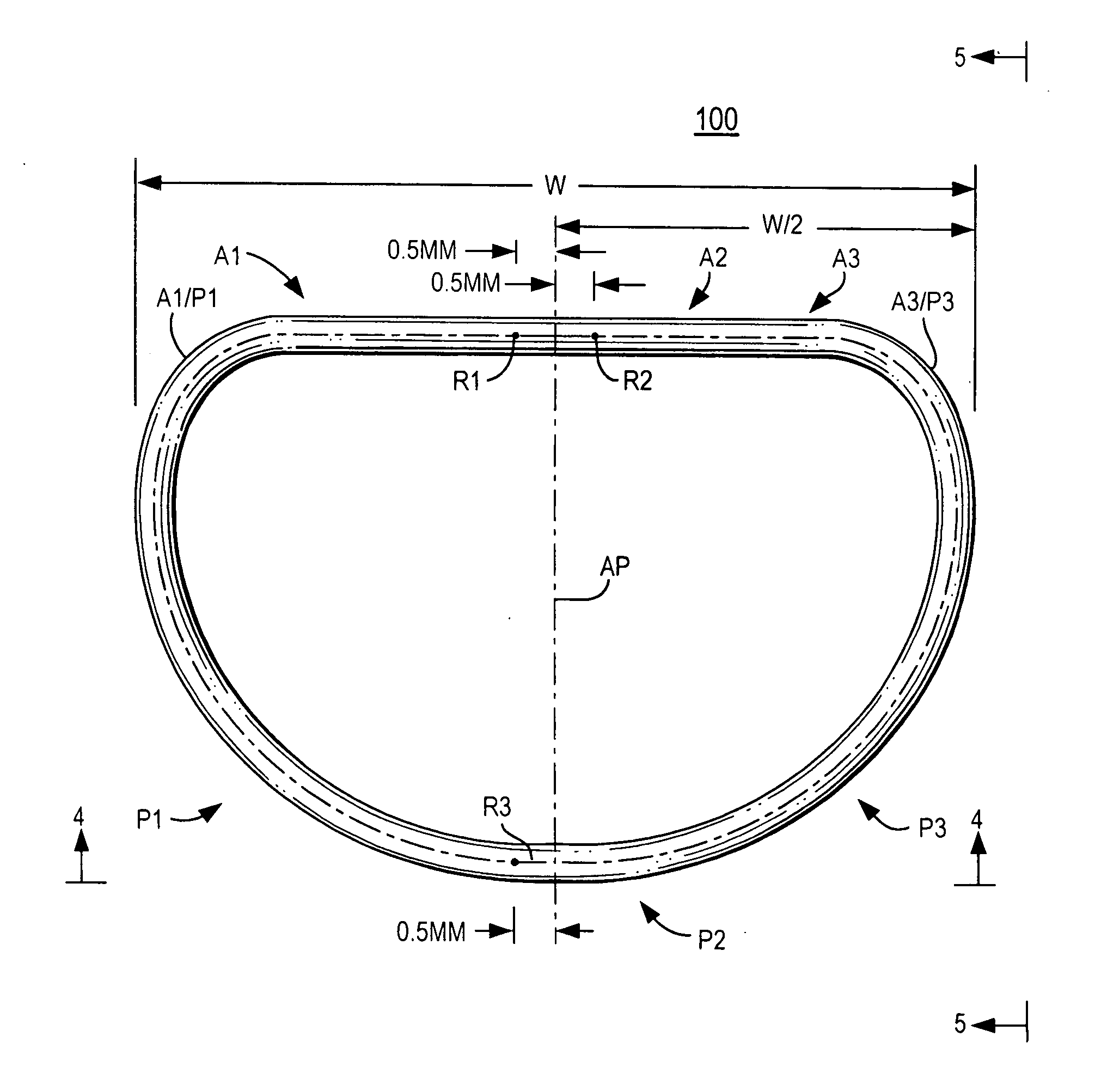
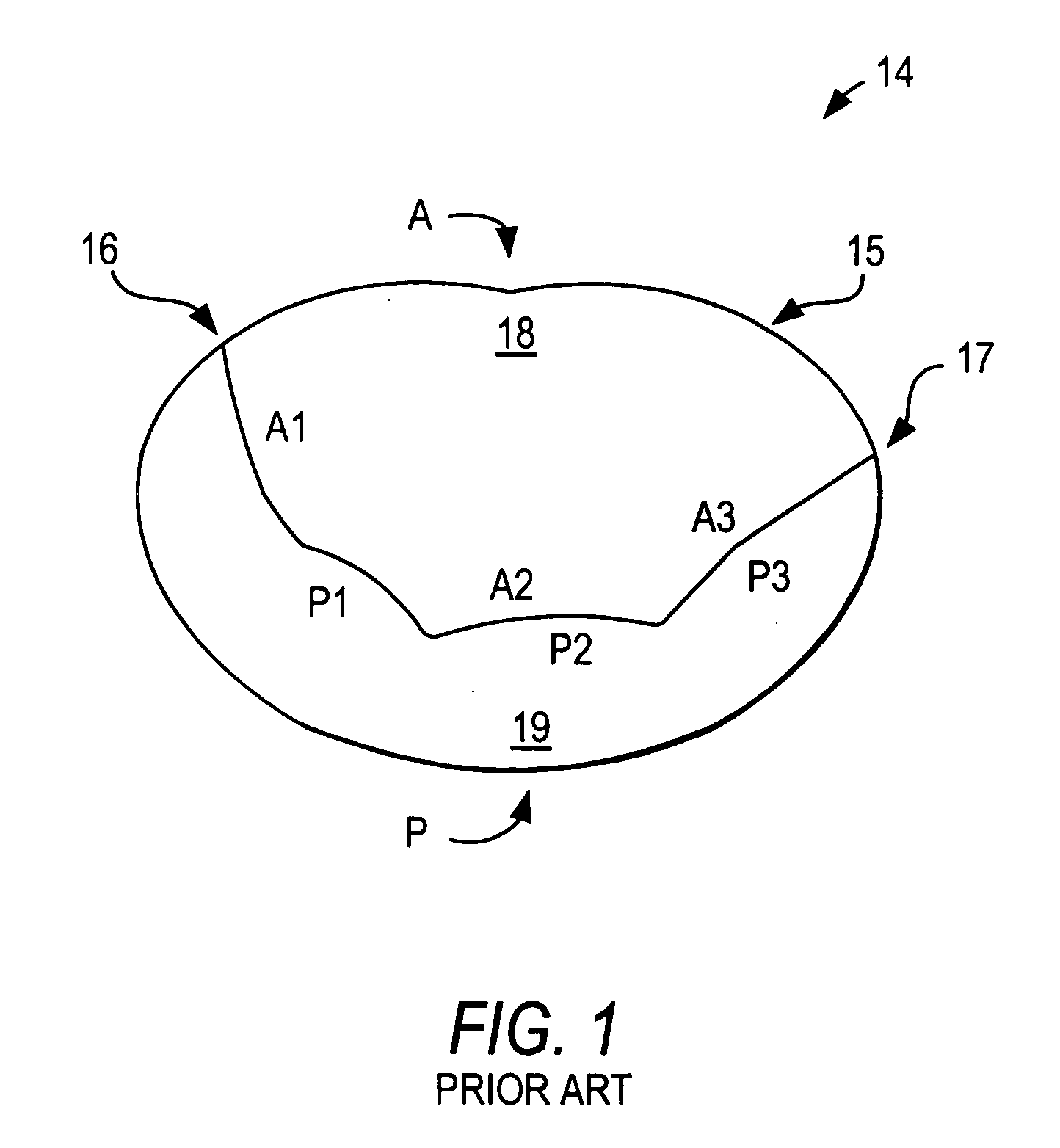
[0021] An illustrative embodiment of a mitral valve annuloplasty ring 100, in accordance with the invention, that is better suited to treating patient conditions like those described in the background section of this specification is shown in FIGS. 3-5. FIG. 3 shows ring 100 in the same orientation as FIG. 1 shows a mitral valve to which ring 100 may be applied. FIG. 3 shows that ring 100 has a generally D shape. The relatively straight side of the D (toward the top in FIG. 3) is the anterior side of the ring in use. The curved side of the D (toward the bottom in FIG. 3) is the posterior side of the ring in use.

[0022] As shown in FIG. 3, ring 100 includes anterior segments A1, A2, and A3, and posterior segments P1, P2, and P3. Each of these segments is radially adjacent but beyond or outside the corresponding portion of the mitral valve leaflets when the ring is in use (i.e., implanted in a patient adjacent the annulus of the patient's mitral valve). Thus, for example, anterior rin...


PUM


Abstract

A mitral valve annuloplasty prosthesis (ring or C) has a generally saddle shape, i.e., portions of the prosthesis that are or will be adjacent the anterior and posterior commissures of the valve are relatively low as compared to at least some other portions of the prosthesis that are or will be between the commissures. However, the saddle shape is asymmetrical, in that the portion that is or will be adjacent the posterior commissure is lower than the portion that is or will be adjacent the anterior commissure.

Description

[0001] This application claims the benefit of U.S. provisional patent application No. 60 / 730,297, filed Oct. 26, 2005, which is hereby incorporated by reference herein in its entirety.FIELD OF THE INVENTION [0002] This invention relates generally to medical devices, and in particular, to annuloplasty rings and other similar prostheses for reshaping the mitral valve annulus of a patient's heart. The invention also relates to methods of using such prostheses. BACKGROUND OF THE INVENTION [0003] The mitral annulus represents the junction of the fibrous and muscular tissue that joins the left atrium and the left ventricle. The mitral valve is a bicuspid valve having a relatively large anterior leaflet that coapts or meets with a smaller posterior leaflet. [0004]FIG. 1 illustrates a normal mitral heart valve 14 from the left atrium from a surgical view of the heart. The anterior portion A of the mitral annulus 15 forms a part of the “cardiac skeleton” and is bounded by anterior and poster...

Claims


Application Information

Patent Timeline
IPC IPC(8): A61F2/24
CPCA61F2/2448
Inventor KRON, IRVING L.KOVACH, MELINDA KAYEMCGILL, TIMOTHY JOHNZENZ--OLSON, NATHANIEL ZACHARIAS
Owner ST JUDE MEDICAL LLC
Why Eureka
Try Eureka