Control device for electric power steering system

a control device and power steering technology, applied in the direction of steering initiation, instruments, vessel construction, etc., can solve the problems of affecting the smooth feeling near the neutral position, affecting the smoothness of steering, and difficult to maintain good steering feelings, so as to improve damping function, improve steering feeling, and reduce the strong back feeling during the steering state

Inactive Publication Date: 2007-05-03
NSK LTD
View PDF7 Cites 19 Cited by
  • Summary
  • Abstract
  • Description
  • Claims
  • Application Information

AI Technical Summary

Benefits of technology

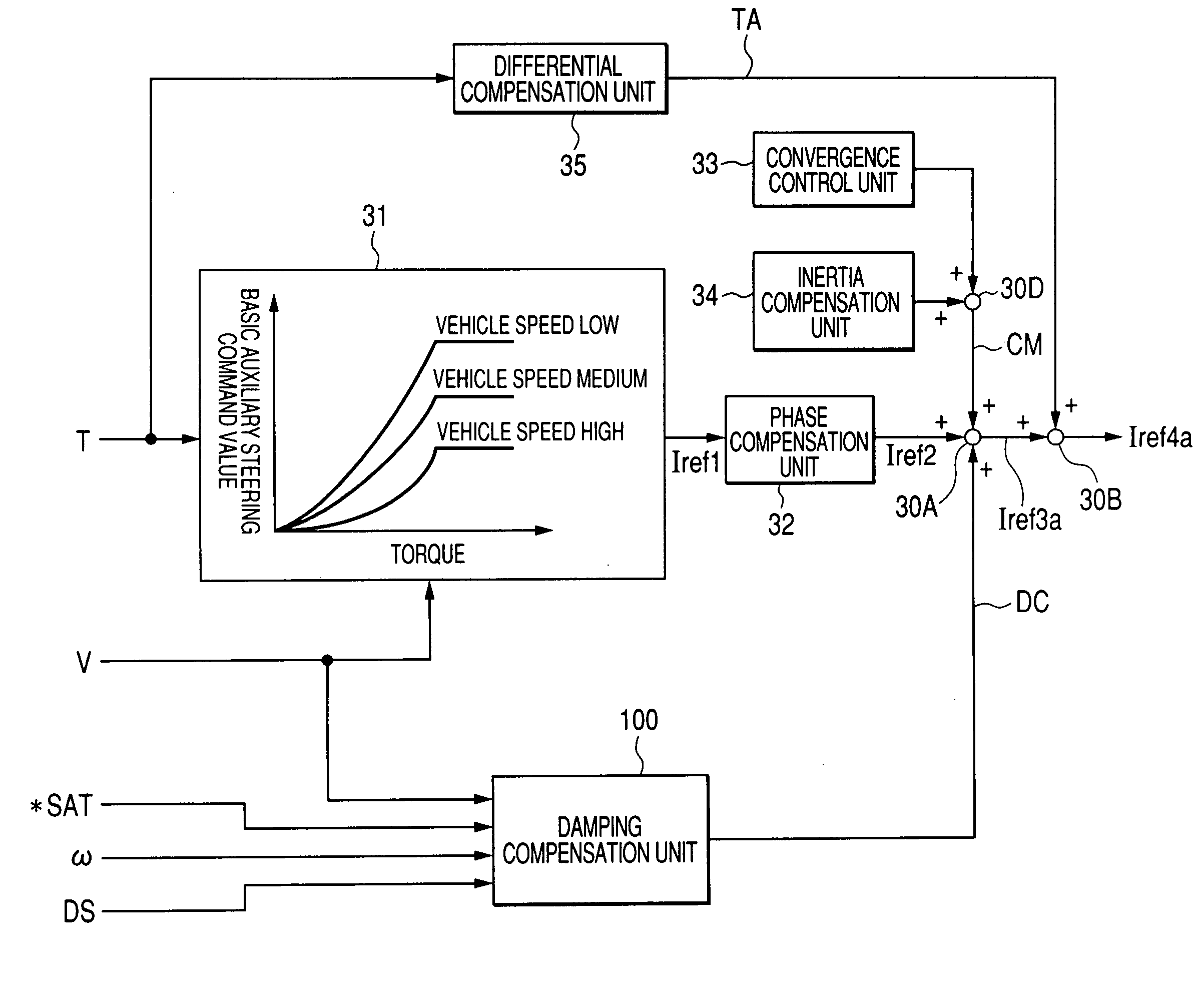
[0017] The present invention is achieved in view of such situations. An object of the invention is to provide a control device for an electric power steering system which has improved damping function and excellent steering feeling in which strong returning feeling during steer-back state is reduced without deteriorating the smooth feeling and the reaction feeling during the operation of the steering.

Problems solved by technology

Therefore, a steering feeling is deteriorated.
Therefore, it is difficult to maintain good steering feelings at near neutral position where SAT is small and at large steering angle position where SAT becomes somewhat larger.
Namely, in order to reduce the strong returning feeling due to a large SAT, a large damping compensation value is applied, thereby impairing the smooth feeling near neutral position.
Furthermore, in JP-A-2004-276821, a damping compensation value is adjusted to be larger when the steering torque is large, but it is insufficient because the steering torque and the SAT do not necessarily coincide.
For example, when an assist map is set such that a maintaining holding torque is light, the steering torque is small even when the restorative force of a vehicle is large, and the damping compensation value does not become larger sufficiently, so that it is not possible to reduce the strong returning feeling sufficiently.
When the adjustment is set large in order to reduce the strong returning feeling, the smooth feeling at near the neutral position is impaired.
Furthermore, in the devices described in the JP-B-2791299 and JP-A-2004-276821, because there is no consideration about distinction between steer-forward state and steer-back state, it is difficult to ensure the smooth feeling and the good (adequate) returning feeling.

Method used


Image

  • Control device for electric power steering system
  • Control device for electric power steering system
  • Control device for electric power steering system

Examples


second embodiment

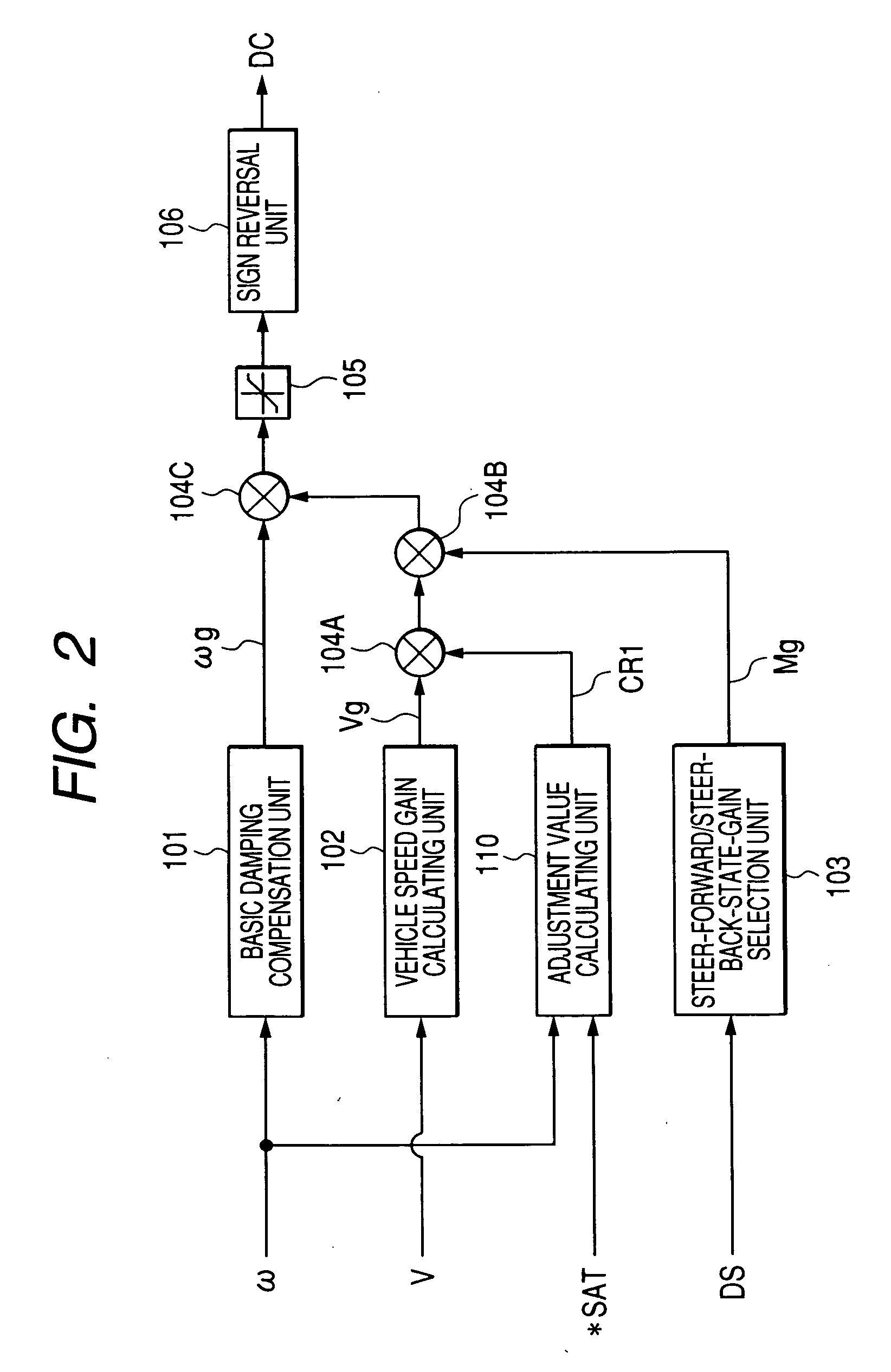
[0085]FIG. 9 shows the damping compensation unit 100 by corresponding to FIG. 2. An adjustment value calculating unit 110A calculates an adjustment value CR2 according to only the SAT estimated value *SAT. It is preferable that the magnitude of the basic damping compensation value ωg and the adjustment value CR2 is determined according to not only the smooth feeling near the neutral position, the reaction feeling during the steer-toward state, the steering wheel returning speed, but also emergency escape performance. The reason is as follows. That is, when the damping is large, since the large steering torque T is required in the case of emergency, escape operation becomes difficult. Meanwhile, if the damping is very small, since the steering torque T is small, the steering wheel is excessively turned, and thus impairing the stability.

third embodiment

[0086]FIG. 10 shows the damping compensation unit 100 by corresponding to FIG. 2. An adjustment value calculating unit 110B calculates an adjustment value CR3 according to the SAT estimated *SAT and the vehicle speed V, and does not have the vehicle speed gain unit calculating the vehicle speed gain Vg. The SAT adjustment value calculating unit in the adjustment value calculating unit 110B outputs a SAT adjustment value CR3 having the characteristics shown in FIGS. 11A or 11B with respect to the absolute value |*SAT|. It is preferable that the magnitude of the basic damping compensation value ωg and the SAT adjustment value CR3 is determined according to not only the smooth feeling near the neutral position, the reaction feeling during the increasing of steering angle, the steering wheel returning speed, but also emergency escape performance.

[0087]FIG. 12 shows a characteristic example of the damping compensation value DC with respect to the high speed and low speed of the vehicle s...

fourth embodiment

[0088]FIG. 13 shows the damping compensation unit 100 by corresponding to FIG. 2. An adjustment value calculating unit 110C calculates an adjustment value CR4 according to the SAT estimated *SAT, the vehicle speed V, and the steer-forward / steer-back state determination signal DS. In addition, the adjustment value calculating unit 110C does not have the vehicle speed gain unit calculating the vehicle speed gain Vg and the steer-forward / steer-back state determination unit. The SAT adjustment value calculating unit in the adjustment value calculating unit 110C outputs a SAT adjustment value CR4 having the characteristics shown in FIGS. 14A or 14B with respect to the absolute value |*SAT|. It is preferable that the magnitude of the basic damping compensation value ωg and the SAT adjustment value CR4 is determined according to not only the smooth feeling near the neutral position, the reaction feeling during the increasing of steering angle, the steering wheel returning speed, but also e...


PUM


Abstract

In a control device for an electric power steering system for controlling a motor on the basis of an auxiliary steering command value calculated from a steering torque generated in a steering shaft and a vehicle speed, and a current detection value of the motor that applies an auxiliary steering force to a steering mechanism, the device comprises a damping compensation unit that calculates a basic damping compensation value on the basis of a steering speed and adjusts the basic damping compensation value on the basis of an SAT estimated value and the steering speed, wherein an adjusted damping compensated value that is adjusted in the damping compensation unit is added to the auxiliary steering command value.

Description

BACKGROUND OF THE INVENTION [0001] 1. Field of the Invention [0002] The present invention relates to a control device for an electric power steering system for applying an auxiliary steering force by a motor to a steering system of an automobile or a vehicle. More particularly, the present invention relates to a control device for an electric power steering system in which a damping function is improved so that a strong (inadequate) return feeling during steering a steering wheel toward neutral position is reduced without impairing a smooth feeling at beginning of steering from a neutral position to a rack end and a reaction feeling during steering further. [0003] Note that the return feeling is a feeling which can be felt where a steered wheel is returned to a neutral position so that a steering angle of the steering wheel becomes smaller, this state is called the steer-back state hereinafter. [0004] The smooth feeling is a feeling which can be felt where a driver begins to steer t...

Claims


Application Information

Patent Timeline
Patent Type & Authority Applications(United States)
IPC IPC(8): B62D6/00
CPCB62D5/0466
Inventor SAKAGUCHI, TORUKOVUDHIKULRUNGSRI, LILIT
Owner NSK LTD
Why Eureka
Try Eureka