System and method for detection and tracking of targets

a target detection and target technology, applied in the field of active and passive sensor applications, can solve the problems of only using sophisticated sensor systems, cost and difficulty in implementation, and passive sensor systems cannot decide on the range and velocity of intercepted transmitters

Inactive Publication Date: 2007-05-10
SIGNAL LABS
View PDF53 Cites 16 Cited by
  • Summary
  • Abstract
  • Description
  • Claims
  • Application Information

AI Technical Summary

Benefits of technology

[0029] The present invention is based on the simultaneous computation of distance and Doppler shift information using fast computation of the ambiguity function and / or Wigner distribution of received signals along on arbitrary line. By using the fractional Fourier transformation of time domain signals, closed form expressions for arbitrary projections of their auto or cross ambiguity function are derived. By utilizing discretization of the obtained analytical expressions, efficient algorithms are proposed in accordance to the present invention to compute uniformly spaced samples of the Wigner distribution and the ambiguity function located on arbitrary line segments. With repeated use of the proposed algorithms, in alternative embodiments of the invention, samples in the Wigner or ambiguity domain can be computed on non-Cartesian sampling grids, such as polar grids, which are the natural sampling grids of chirp-like signals. The ability to obtain samples of the Wigner distribution and ambiguity function over both rectangular and polar grids is potentially useful in a wide variety of application areas, including time-frequency domain kernel design, multicomponent signal analysis, time-frequency domain signal detection and particle location analysis in Fresnel holograms.

Problems solved by technology

Although the use of the cross-ambiguity function for detection of scattering objects and estimation of their corresponding delay and Doppler shifts is known in the prior art, this approach has only been used in sophisticated sensor systems because of the high cost and difficulty of implementation.
Therefore, in most of the applications where the cost is a critical issue, the sensor systems are designed to detect the presence of scattering objects and estimate either their range or their velocities, but not both.
Unlike the active sensor systems where the range and the velocity of the objects can be estimated from the reflected signals, passive sensor systems cannot decide on the range and the velocity of the intercepted transmitter without extensive prior information about the transmitter.
As seen from FIG. 2B, the detection of the signal can be a difficult task, especially for intercepted signals that have low amplitudes.
However, in practice the auto-ambiguity function approach is almost never used in the detection of intercepted signals due to the associated high cost and complexity.

Method used


Image

  • System and method for detection and tracking of targets
  • System and method for detection and tracking of targets
  • System and method for detection and tracking of targets

Examples


first embodiment

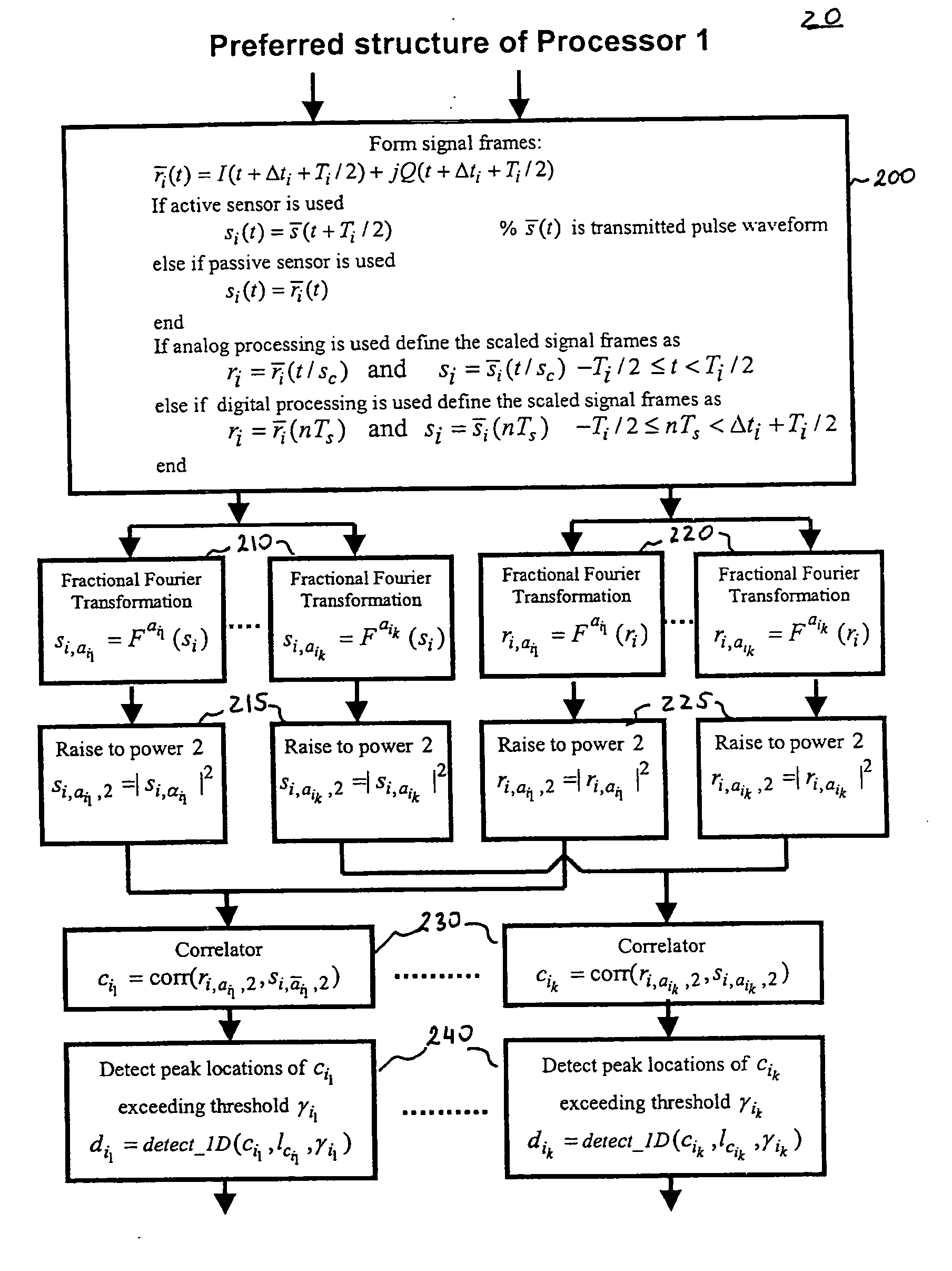
[0069] The preferred configuration of the first embodiment shown in FIG. 9 is designed for both the active and passive sensor systems. In the case of active sensor applications, si in block FIG. 9 is set to be the transmitted signal delayed with Ti / 2. In the case of passive sensor applications, si in block FIG. 9 is set to be the i-th received signal frame. Then, si is also transformed into multiple fractional Fourier domains In the preferred configuration, the orders of the fractional Fourier transformations are chosen to be the same as the orders used in the fractional Fourier transformations applied on the received signal frame in 220. Therefore, in passive sensor applications, the fractional Fourier transformations of si are identical to those of ri. Hence, it is not necessary to compute the fractional Fourier transformations of si. In the case of active sensor applications with a digital receiver, such a computational efficiency can be achieved by computing the required fractio...

second embodiment

[0081] In the case of multiple peaks detected on individual correlations, in accordance with the invention the corresponding peak locations of the Ari,si(τ, v). can be found in many alternative methods. To introduce some of these alternatives, a simple case of detection of two scattering objects on two different projections is shown in FIG. 22. The potential locations of the peaks in Ari,si(τ,v) are at the four intersections shown in FIG. 22. The decision in the actual locations can be based on computing values of Ari,si(τ,v) around these four intersection points by using the algorithm given in Appendix B. This method is shown as part of the preferred structure of the second embodiment in FIG. 10. If there is a significant difference between the magnitudes of the detected peaks on each correlation, in accordance with a second alternative method, the location of the peaks in Ari,si(τ,v) can be estimated as the intersection of those perpendicular lines which correspond to the similar ...


PUM


Abstract

System and method for detection and tracking of targets, which in a preferred embodiment is based on the use of fractional Fourier transformation of time-domain signals to compute projections of the auto and cross ambiguity functions along arbitrary line segments. The efficient computational algorithms of the preferred embodiment are used to detect the position and estimate the velocity of signals, such as those encountered by active or passive sensor systems. Various applications of the proposed algorithm in the analysis of time-frequency domain signals are also disclosed.

Description

CLAIM OF PRIORITY [0001] This application is a continuation of U.S. patent application Ser. No. 10 / 691,245 filed on Oct. 21, 2003, which in turn is a continuation of U.S. patent application Ser. No. 09 / 875,116 filed Jun. 6, 2001, issued as U.S. Pat. No. 6,636,174, which in turn claims priority of provisional application Ser. No. 60 / 209,758 filed Jun. 6, 2000.FIELD OF THE INVENTION [0002] The present invention relates to active and passive sensor applications, and more particularly is directed to efficient systems and methods for detection and tracking of one or more targets. BACKGROUND OF THE INVENTION [0003] Detection and tracking of targets by sensor systems have been the subject matter of a large number of practical applications. Sensor systems designed for this purpose may use propagating wave signals, such as electromagnetic or acoustical signals. Some sensor systems, such as radar and active sonar systems, are designed to receive reflections of a transmitted signal generated b...

Claims


Application Information

Patent Timeline
Patent Type & Authority Applications(United States)
IPC IPC(8): G01S13/00G01S7/295G01S13/524
CPCG01S7/295G01S13/524
Inventor ARIKAN, ORHANOZDEMIR, AHMET KEMAL
Owner SIGNAL LABS
Why Eureka
Try Eureka