Touchscreen device for controlling a security system

a technology of security system and touch screen, which is applied in the field of security system, can solve the problems of security system being put in an undesirable mode, limit the amount of controllable functions the device can perform, and the button on the device being subject to inadvertent activation

Active Publication Date: 2007-05-10
ADEMCO INC
View PDF4 Cites 140 Cited by
  • Summary
  • Abstract
  • Description
  • Claims
  • Application Information

AI Technical Summary

Benefits of technology

[0012] The security device also comprises a display such as an LCD display for displaying alpha numeric control options to be selected by a user and LED indicators for indicating the modes of the processing circuitry. In an alternative embodiment the LCD display may contain graphics that indicate the modes of the processing circuitry. The user views the control options displayed on the LCD and uses the contact motions on the touch-pad as described above to either (1) select the current control option displayed, (2) scroll to a different control option, or (3) go into a programming mode. In order to perform these operations, the security device processing circuitry uses a micro-computer to input the control signals from the touch-pad device and, depending on the control signal, the micro-computer outputs signals to the LCD display, the LED indicators, and / or the RF transmitter. In order to provide flexibility to the user, the control options are programmed into the security device by an installer (or the user) when the security device is put into the programming mode.
[0014] The method of operation of the present invention is as follows. The user views the control option on the security device display and performs a contact motion on the touch-pad. The touch-pad provides a control signal to the processing circuitry that corresponds to the contact motion, and the processing circuitry determines the processing state based on the control signal. If the processing state is a first level processing state, then the processing circuitry transmits to the security system an output signal which is a function of the control signal. An example of a first level processing state would be an execute input which may be a left to right finger swipe contact motion. This indicates acceptance of the currently displayed control option. A first level processing state requires no further input from the user. If the processing state is a second level processing state, then the processing circuitry revises the control option displayed to the user, accepts a subsequent user input into the touch-pad, and converts the subsequent user input into a control signal related to the subsequent user input. These steps may be repeated. An example of a second level processing state would be a mode select input which may be a right to left finger swipe contact motion. A second level processing state requires an additional input from the user. The present invention also comprises the step of indicating the mode of the processing circuitry by illuminating LEDs, which helps the user to know if the security device is executing a command or waiting for an input. In an alternative embodiment, the step of indicating the mode of the processing circuitry is performed by the LCD display which contains graphics that indicate the modes of the processing circuitry.

Problems solved by technology

The small number of buttons is a problem for security system control devices because it limits the amount of controllable functions the device can perform.
An additional concern of a wireless handheld device is that the buttons on the device are subject to inadvertent activation when something rubs against the device.
This may cause the security system to be put in an undesirable mode.

Method used


Image

  • Touchscreen device for controlling a security system
  • Touchscreen device for controlling a security system
  • Touchscreen device for controlling a security system

Examples


Embodiment Construction

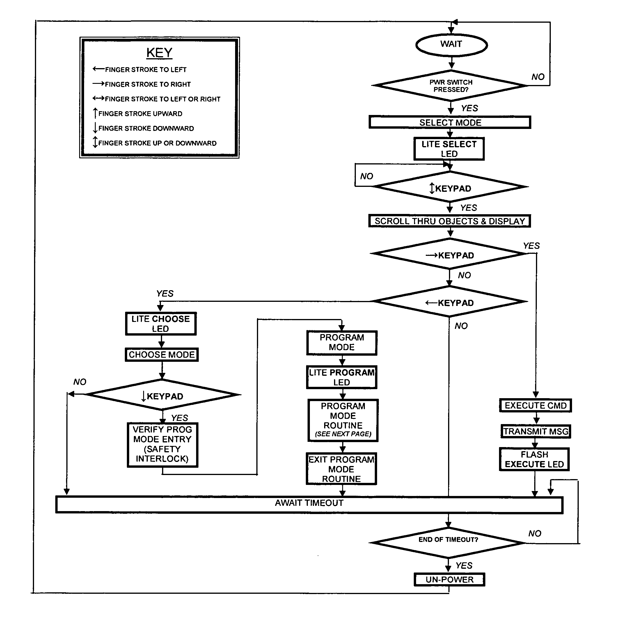
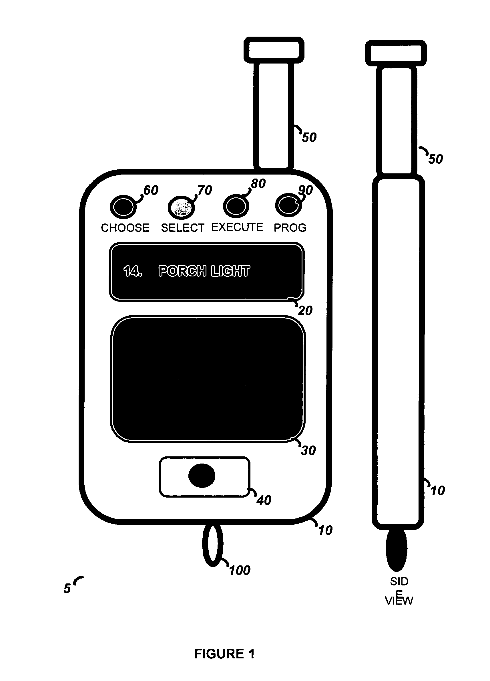
[0018] The preferred embodiments of the present invention will now be described with respect to the Figures. FIG. 1 illustrates the security device 5 as a key fob. Shown are front and side views of the key fob housing 10. The key fob housing 10 has an antenna 50 and a keychain loop 100 attached to it. The antenna 50 provides a large transmission range, while the keychain loop 100 allows the security device 5 to be easily attached to a keychain. The antenna 50 may be extendable, fully retractable, or built-in (totally internal). The key fob housing 10 contains a recessed power on button 40, an LCD display 20, a touch pad 30, and four LEDs 60, 70, 80, and 90. The power button is pushed to turn the security device 5 on. If it is turned on accidentally, it will turn itself off after a short time of inactivity because it will interpret inactivity as no valid user input on the touch pad 30. Once the security device 5 is turned on, the LCD display 20 will be lit by the backlight LED 110 an...


PUM


Abstract

The present invention is a hand held portable remote such as a key fob that allows a user to interact with the security system using a flat panel touch-pad. The touch-pad input allows a user to rapidly select and control a large number of security functions, such as Arm, Disarm, Panic, garage door open, lamp on / off, and lamp dimming control, etc. The security device comprises a housing, a wireless communication port for interface with the security system, a touch-pad input device, and processing circuitry. In order to operate the security device, the user generates a user input by creating a contact motion on the touch-pad input device with a fingertip. The contact motion may consist of a swiping motion, a tapping, or a circular motion. In order to distinguish the contact motion clearly, when the fingertip contact comprises a wider than normal contact, it causes the processing circuitry to not generate an output signal. The security device also comprises an LCD display for displaying alpha numeric control options to a user and LED indicators for indicating the modes of the processing circuitry.

Description

TECHNICAL FIELD [0001] This invention relates to security systems, and in particular to a control device with a touch-screen or touch-pad that is used to control a security system. BACKGROUND ART [0002] Nearly all security systems of today utilize sophisticated control devices to perform the functions of programming the security system, arming or disarming the security system, providing a panic alert, controlling lighting, and controlling garage doors, etc. Many security systems employ multiple control devices to allow a user more flexibility in controlling the security system. The control devices may be wired or wireless wall-mounted control panels located at different entrances to the protected area or wireless portable handheld devices that can control the security system from outside the protected area. [0003] A convenient embodiment of a wireless handheld device is a key fob that is small enough to be placed on a key chain. Key fobs are customarily used for locking and unlockin...

Claims


Application Information

Patent Timeline
Patent Type & Authority Applications(United States)
IPC IPC(8): G09G5/00G06F13/42G08B23/00
CPCG08B25/008G08B25/016
Inventor KATZ, FRED
Owner ADEMCO INC
Why Eureka
Try Eureka