Plasma television and panel type television

a panel type and television technology, applied in the field of plasma television and panel type television, can solve the problems of reducing work efficiency, affecting the appearance quality of the television, and affecting the appearance quality of the television, and achieve the effect of more inexpensive panel type television and cost reduction

Inactive Publication Date: 2007-05-10
FUNAI ELECTRIC CO LTD
View PDF8 Cites 33 Cited by
  • Summary
  • Abstract
  • Description
  • Claims
  • Application Information

AI Technical Summary

Benefits of technology

[0010] The present invention discloses a panel type television and a plasma television in which the number of parts thereof is reduced and which facilitate saving of the labor of mounting works, reducing of mounting defects and cutting of costs.
[0014] According to the present invention, the protruding sections are provided at the vertically extending bridge frames and the screw-fixation sections are formed by causing the protruding sections to be bent, so that it is possible to cause the vertically extending bridge frames to be screw-fastened directly to the back face of the PDP module. This will enable the number of parts to be considerably reduced from six to two, enable the labor of assembling work to be saved, and enable the mounting defects to be reduced. Moreover, spacers which are made of expensive nylon resins are not required, thus cutting costs. Therefore, according to the present invention, it is possible to provide an inexpensive panel type television.
[0016] That is, if each of the first and third hole means formed in the upper left screw-fixation section and the lower left screw-fixation section, respectively, comprises plural threaded round-holes, each of the second and fourth hole means formed in the upper right screw-fixation section and the lower right screw-fixation section, respectively, comprises a threaded oblong hole extending laterally. Also, if each of the second and fourth hole means formed in the upper right screw-fixation section and the lower right screw-fixation section, respectively, comprises plural threaded round-holes, each of the first and third hole means formed in the upper left screw-fixation section and the lower left screw-fixation section, respectively, comprises an oblong threaded-hole extending laterally. This enables mounting of a display panel of a number of kinds to be performed by utilizing the same vertically extending bridge frames, even if the display panel is designed by a panel maker such that a mounting position of the display panel is varied. Therefore, it is unnecessary to prepare vertically extending bridge frames which are exclusive per display panel which is supplied by the panel maker, so that it is possible to cut costs and provide a more inexpensive panel type television.

Problems solved by technology

This will take a great deal of trouble.
This will contribute to reduction of work efficiency at the time of assembling and also contribute to mounting defects.
Moreover, the spacers are generally made of relatively expensive nylon resins, so that it is hard to cut costs.

Method used


Image

  • Plasma television and panel type television
  • Plasma television and panel type television
  • Plasma television and panel type television

Examples


Embodiment Construction

[0027] The detailed description set forth below in connection with the appended drawings is intended as a description of presently preferred embodiments of the invention and is not intended to represent the only forms in which the present invention may be constructed and or utilized.

[0028] An embodiment according to the present invention will be discussed hereinafter in the following order.

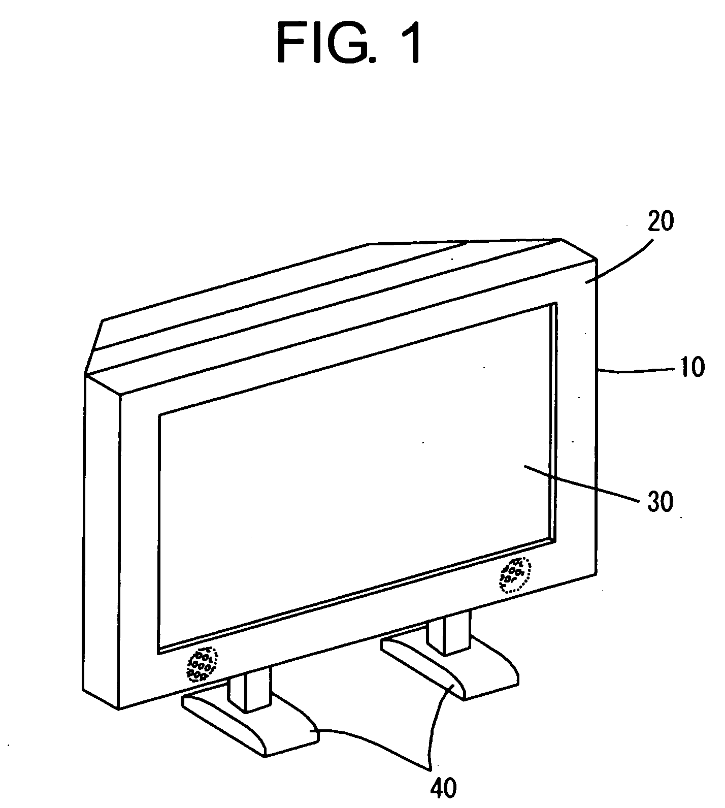
[0029] (1) Structure of a panel type television;

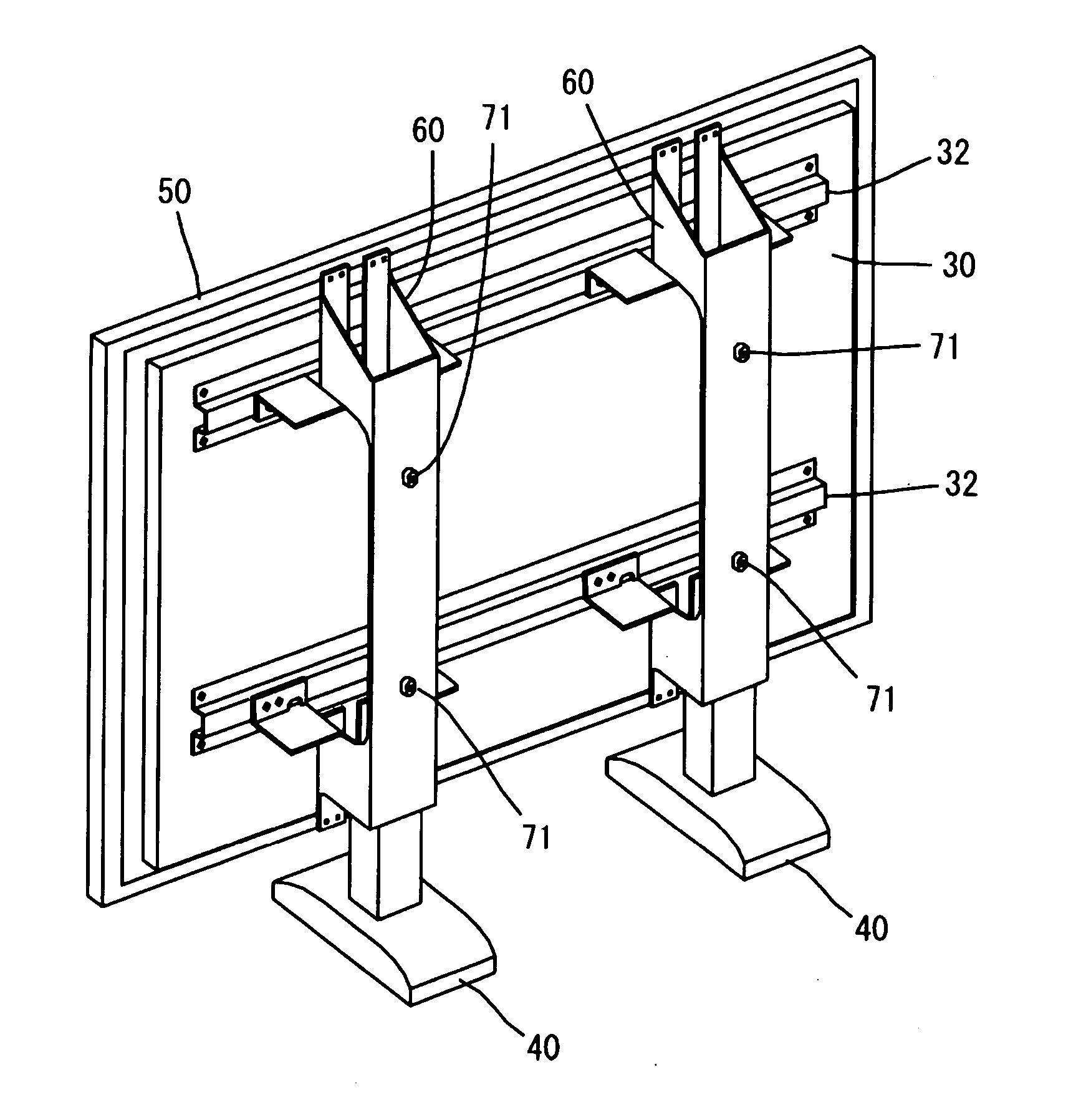
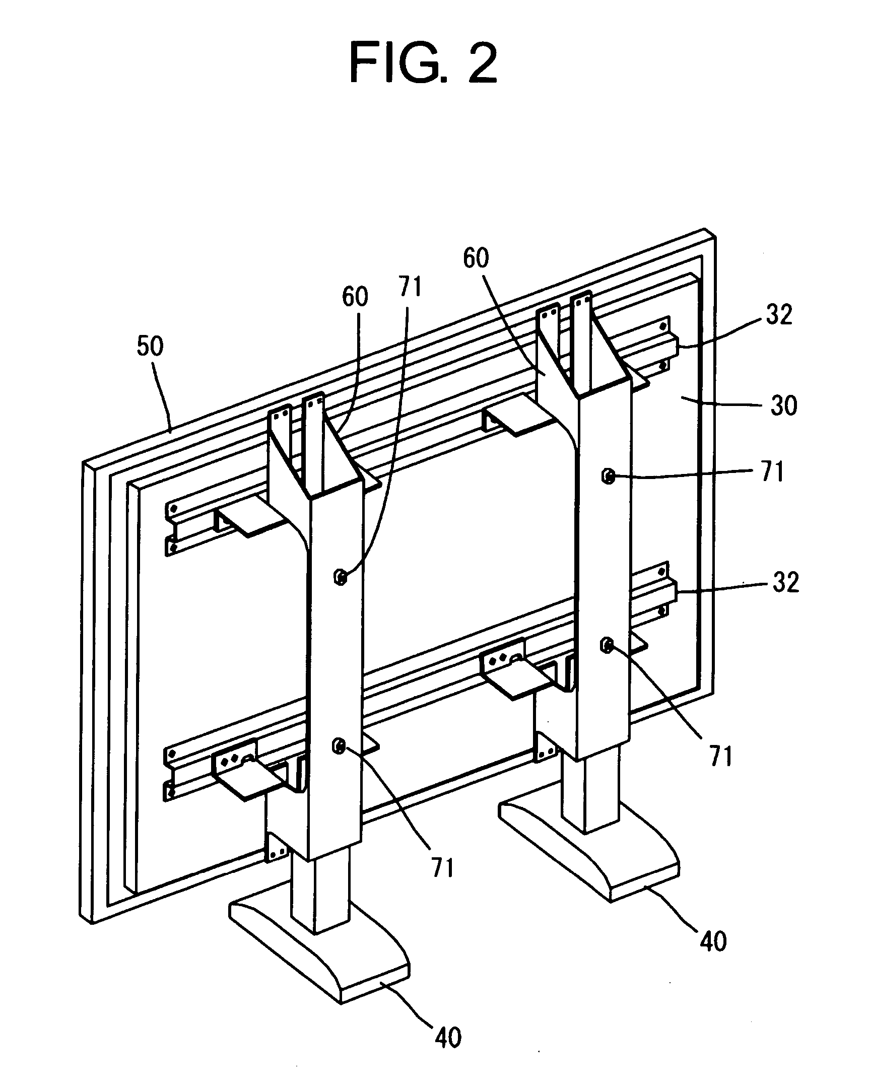
[0030] (2) Structure of a vertically extending bridge frame; and

[0031] (3) Summary

[0032] (1) Structure of a Panel Type Television:

[0033] Referring to FIG. 1, there is illustrated a panel type television 10, as viewed from an oblique front side, which employs a plasma display panel (PDP) module. In the illustrated example, a cabinet means 20 comprises a thin housing which has a substantially rectangular shape extending laterally. The cabinet housing comprises a front cabinet member having a substantially rectangular opening formed in a front sur...


PUM


Abstract

An upper left protruding section 63a, an upper right protruding section 63b, a lower left protruding section 64a, and a lower right protruding section 64b are provided at vertically extending bridge frames 60, and an upper left screw-fixation section 65a, an upper right screw-fixation section 65b, a lower left screw-fixation section 66a, and a lower right screw-fixation section 66b are formed by causing the respective protruding sections to be bent, so that it is possible to cause the vertically extending bridge frames 60 to be screw-fastened directly to a back face of a PDP module 30. Accordingly, it is possible to reduce the number of parts, save the labor of assembling work, reduce the mounting defects, and cut costs.

Description

CROSS-REFERENCES TO RELATED APPLICATIONS [0001] The present application is related to the Japanese Utility Model Application No. 2005-009240, filed Nov. 4, 2005, the entire disclosure of which is expressly incorporated by reference herein. BACKGROUND OF THE INVENTION [0002] (1) Field of the Invention [0003] This invention relates to a plasma television and a panel type television. [0004] (2) Description of the Related Art [0005] Referring now to FIG. 7, a conventional plasma television having a plasma display panel (PDP) module will be discussed hereinafter in order to facilitate understanding of the present invention. In the conventional plasma television of FIG. 7, a pair of vertically spaced apart spacers 92 and a pair of vertically spaced apart lower spacers 92 are arranged on the left and right sides of a back face of the PDP module 90, and two vertically extending bridge frames 93 are arranged on the upper and lower spacers 92 so as to be spaced apart at a predetermined interv...

Claims


Application Information

Patent Timeline
Patent Type & Authority Applications(United States)
IPC IPC(8): H04N3/12
CPCF16M11/00F16M11/02F16M11/22F16M2200/08H04N5/64
Inventor MARUTA, NAOTO
Owner FUNAI ELECTRIC CO LTD
Why Eureka
Try Eureka