Linear compressor

a linear compressor and compressor technology, applied in the direction of machines/engines, positive displacement liquid engines, piston pumps, etc., can solve the problems of increased manufacturing costs and difficult assembly work, and achieve the reduction of manufacturing costs and assembly time of linear compressors, simplified oil supply structures, and reduced oil supply parts.

Inactive Publication Date: 2007-05-10
LG ELECTRONICS INC
View PDF8 Cites 4 Cited by
  • Summary
  • Abstract
  • Description
  • Claims
  • Application Information

AI Technical Summary

Benefits of technology

[0030] In the linear compressor of the present invention having the above-described configuration, the piston and the cylinder are arranged to extend vertically in the shell, and the plurality of oil suction paths are perforated through the cylinder for introducing oil, stored in the shell, into a space between the cylinder and the piston without requiring separate pumping means, whereby the oil supply structure can be simplified with a reduced number of oil supply parts, and therefore, the manufacturing costs and assembling time of the linear compressor can be reduced.
[0031] Further, when the oil storage portion is defined in a space between the cylin

Problems solved by technology

A problem of the conventional linear compressor is that it requires many oil pumping parts, such as for example, the oil cylinder 44, oil piston 45, f

Method used


Image

  • Linear compressor
  • Linear compressor
  • Linear compressor

Examples


first embodiment

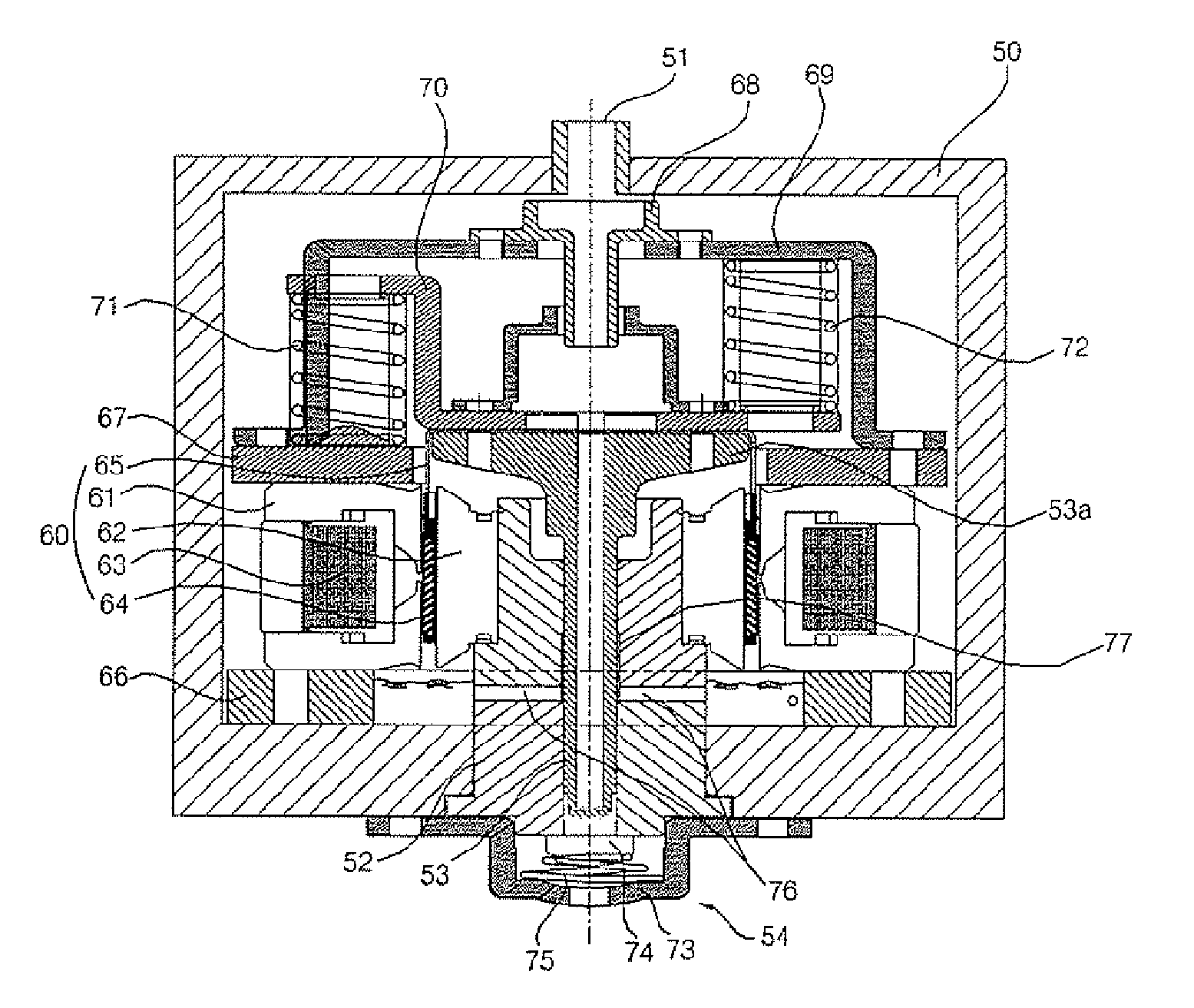
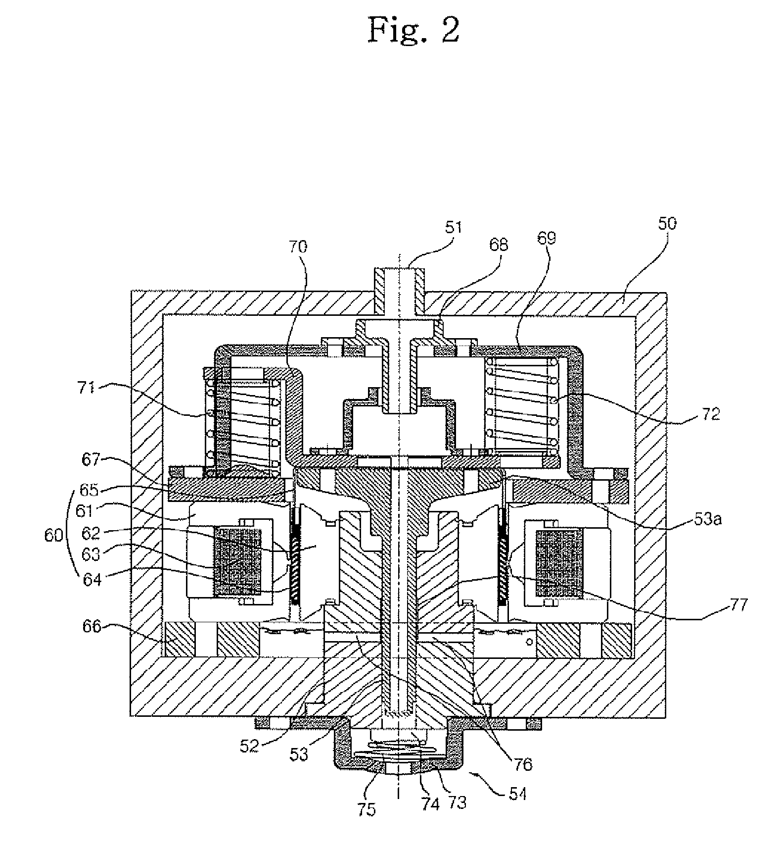
[0039]FIG. 2 is a sectional view illustrating a linear compressor according to the present invention.

[0040] As shown in FIG. 2, the linear compressor according to the first embodiment of the present invention comprises a shell 50 formed with a suction port 51 and a discharge port, an elongated cylinder 52 extending vertically in the shell 50, a piston 53 disposed in the cylinder 52 to perform linear reciprocating movements in the cylinder 52, a linear motor 60 to linearly reciprocate the piston 53, a discharge unit assembly 54 mounted to the discharge port at the outside of the shell 50 to allow the fluid, compressed in the cylinder 52, to be discharged through the discharge unit assembly 54, and an oil supply device formed in the cylinder 52 to supply oil into a space between the cylinder 52 and the piston 53.

[0041] The shell 50 has a cylindrical structure, and is provided at the top thereof with the suction port 51 and at the bottom thereof with the discharge port.

[0042] The cyl...

second embodiment

[0064]FIG. 3 is a sectional view illustrating a linear compressor according to the present invention.

[0065] As shown in FIG. 3, the linear compressor according to the second embodiment of the present invention comprises a shell 80 formed with a suction port 81 and a discharge port, an elongated cylinder 82 extending vertically in the shell 80, a piston 83 disposed in the cylinder 82 to perform linear reciprocating movements, a linear motor 84 to linearly reciprocate the piston 83 up and down, a discharge unit assembly 85 mounted to the discharge port at the outside of the shell 80 to allow the fluid, compressed in the cylinder 82, to be discharged through the discharge unit assembly 35, and an oil supply device formed in the cylinder 82 to supply oil into a space between the cylinder 82 and the piston 83.

[0066] In the present embodiment, a motor holder 90 is provided around the cylinder 82 to secure the linear motor 84.

[0067] The motor holder 90 has a cylindrical shape, and is rad...


PUM


Abstract

Disclosed herein is a linear compressor wherein a piston and a cylinder are arranged to extend vertically in a shell, and oil suction paths are formed in the cylinder for introducing oil stored in the shell into a space between the cylinder and the piston without requiring oil pumping parts, whereby a simplified oil supply structure can be accomplished via a reduced number of parts, and therefore, manufacturing costs and assembling time can be reduced.

Description

BACKGROUND OF THE INVENTION [0001] 1. Field of the Invention [0002] The present invention relates to a linear compressor, and more particularly, to a linear compressor in which a piston and a cylinder are arranged to extend vertically and oil suction paths are perforated through a wall of the cylinder to supply oil into the cylinder, whereby the oil supply structure of the compressor is simplified, and thus, manufacturing costs and assembling time of the compressor can be reduced. [0003] 2. Description of the Related Art [0004] Generally, a linear compressor is an apparatus configured in such a fashion that a piston reciprocally moves in a cylinder upon receiving a linear drive force of a linear motor to perform suction, compression, and discharge operations of fluid, such as gaseous refrigerant, (hereinafter, referred to as “fluid”). [0005]FIG. 1 is a sectional view illustrating a conventional linear compressor. [0006] As shown in FIG. 1, the conventional linear compressor comprise...

Claims


Application Information

Patent Timeline
IPC IPC(8): F04B17/04
CPCF04B35/045F04B39/023F04B39/0276F04B39/0292F04B39/121F05B2210/12F05B2210/14F16N13/06F16N2210/16Y10S417/902
Inventor PARK, HONG HEEHWANG, SEON WOONGCHOI, KI CHUL
Owner LG ELECTRONICS INC
Why Eureka
Try Eureka