
Laminate with optical structure and method for using the same

Inactive Publication Date: 2007-05-10
CHIANG WHE YI +1
View PDF10 Cites 8 Cited by
  • Summary
  • Abstract
  • Description
  • Claims
  • Application Information

AI Technical Summary

Benefits of technology

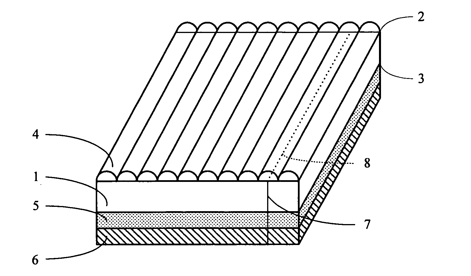
[0008] One object of the present invention is provide a laminate with optical structure a method for using the same to easily and economically create lenticular effects.
[0015] The area of the release layer is larger than that of the adhesive layer for easily utilizing the laminate.
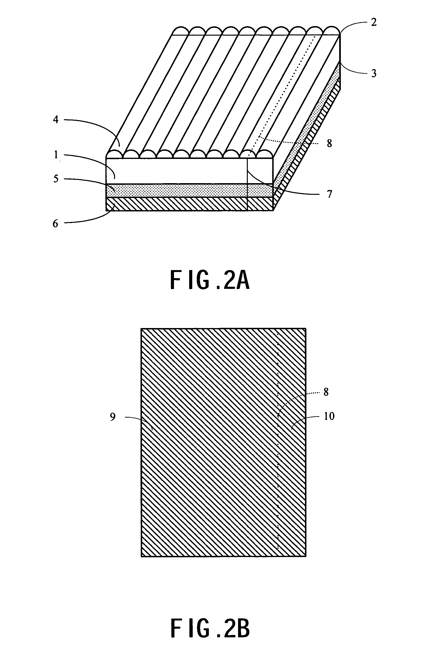
[0018] By removing a part of the release layer and keep the part of the laminate corresponding to the second portion of the release layer away from the alignment plane of the laminate and the output body, the adjustment of the relative position of the laminate and the output body can be carried out easily, smoothly, and precisely. After the correct position is found, the laminate and the output body can be adhered together by pressing down the part of the laminate that was previously bent away from the plane. Finally, the rest of the release layer can be removed to adhere the laminate and the output body gradually from the edge to prevent bubble enclosure.
[0019] Therefore, according to the present invention, laminating the laminate with optical structure with the interlaced image output can create lenticular effects.

Problems solved by technology

Under such condition, the lenticular lens sheet backed with tape slightly adheres to the interlaced image printout, resulting in the difficulty of adjusting the relative position of the image stripe and the lenticular lens.
Thus, it is difficult to do alignment between the interlaced image printout and the lenticular lens sheet.

Method used


Image

  • Laminate with optical structure and method for using the same
  • Laminate with optical structure and method for using the same
  • Laminate with optical structure and method for using the same

Examples


Embodiment Construction

[0026] What is probed into the invention is a laminate with optical structure and a method for using the same. Detail descriptions of the structure and elements will be provided in the following in order to make the invention thoroughly understood. Obviously, the application of the invention is not confined to specific details familiar to those who are skilled in the art. On the other hand, the common structures and elements that are known to everyone are not described in details to avoid unnecessary limits of the invention. Some preferred embodiments of the present invention will now be described in greater detail in the following. However, it should be recognized that the present invention can be practiced in a wide range of other embodiments besides those explicitly described, that is, this invention can also be applied extensively to other embodiments, and the scope of the present invention is expressly not limited except as specified in the accompanying claims.

[0027] The first...


PUM


Abstract

This invention provides a laminate with optical structure and method for using the same. The laminate according to the invention can produce various two-dimensional (2D) or three-dimensional (3D) effects, such as flip, animation, morph, zoom, and 3D effects, by laminating with a specially computer treated image. The objective of this invention is to solve the alignment problem between the optical structure and the image during lamination. By using the laminate from the invention, it is possible to easily align the optical structure with the image to economically obtain an object with 2D animation or 3D effect without using expansive printing equipment.

Description

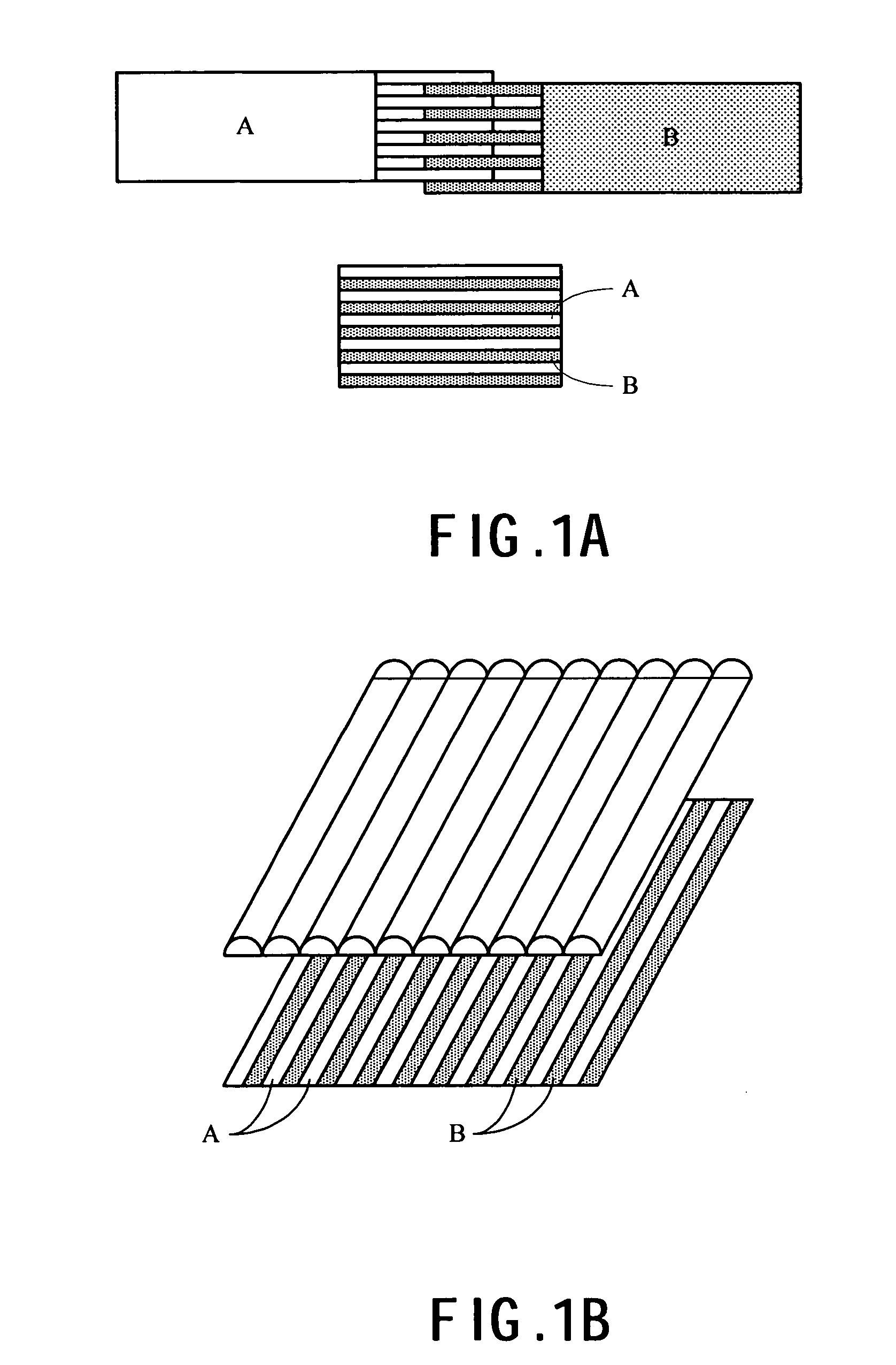
BACKGROUND OF THE INVENTION [0001] 1. Field of the Invention [0002] The present invention is generally related to a laminate with optical structure and a method for using the same, and more particularly to a laminate with lenticular lens to create 2D or 3D effects by laminating with a specially computer treated image. [0003] 2. Description of the Prior Art [0004] There are various different forms of lenticular effects: 3D, flip, animation, morph and zoom. For example, as shown in FIG. 1 the method to create lenticular effects, such as flip effect, is to have A and B image files divided into stripes and interlaced together into an image file (FIG. 1A), to align the interlaced image printout with the lenticular lens sheet or directly print the interlaced image on the lenticular lens sheet (FIG. 1B). The different images A and B can be delivered to each eye from different viewing angle to create flip effect. [0005] However, in order to align the interlaced image printout with the lenti...

Claims


Application Information

Patent Timeline
IPC IPC(8): B32B33/00G02B30/27
CPCB44F1/10G02B3/005Y10T428/2457G02B27/2214Y10T428/14G02B3/06G02B30/27
Inventor CHIANG, WHE-YIPONG, TA-CHING
Owner CHIANG WHE YI
Learn More