
Assembled shelf

Inactive Publication Date: 2007-05-17
I JANG IND
View PDF0 Cites 34 Cited by
  • Summary
  • Abstract
  • Description
  • Claims
  • Application Information

AI Technical Summary

Benefits of technology

[0013] 1. It is applied so that the shelf and vertical side rack do not need other positioning components to achieve positioning, making the present invention more effective and practical.
[0014] 2. The secondary bar provides the common vertical side rack commonly used by the shelf, greatly reducing the cost for shelf and being economical.
[0015] 3. The reinforced stand is placed between the ⊂ shaped bars are to support the strengthen layer board, so that the shelf may hold heavier objects, increasing the practicality.
[0017] 5. Using the design of the insert groove formed by a bent slab to place the groove over the two sides of the shelf plank, the layer board cannot be lifted, which makes it more stable and beautiful. The bottom of the insert groove protrudes inside more than the top. One end may be inserted into the insert groove on the one side, and the other end may be inserted into the insert groove on the other side, making the assembly more convenient.

Problems solved by technology

However, the current assembled structure still has the following issues:
Because the parts of the shelf that need hardware exceeds ten places, it is time consuming.
Because there is no common structure between them, it lacks a stable connection, and the cost is high as well.
The weight limitation is limited when the shelf is being used, and the shelf is unable to take objects that are too heavy.
The common solution is to place a board or iron board between the boards or bars to achieve the objective; however, such a solution affects the entire look of the shelf.
Most of the time, the conventional shelf places a layer board on the frame and is unable to secure the layer board, so that layer board sometime flips, when it is under the outside force, lacking of stability.

Method used


Image

  • Assembled shelf
  • Assembled shelf
  • Assembled shelf

Examples


Embodiment Construction

[0035] The features and the advantages of the present invention will be more readily understood upon a thoughtful deliberation of the following detailed description of a preferred embodiment of the present invention with reference to the accompanying drawings.

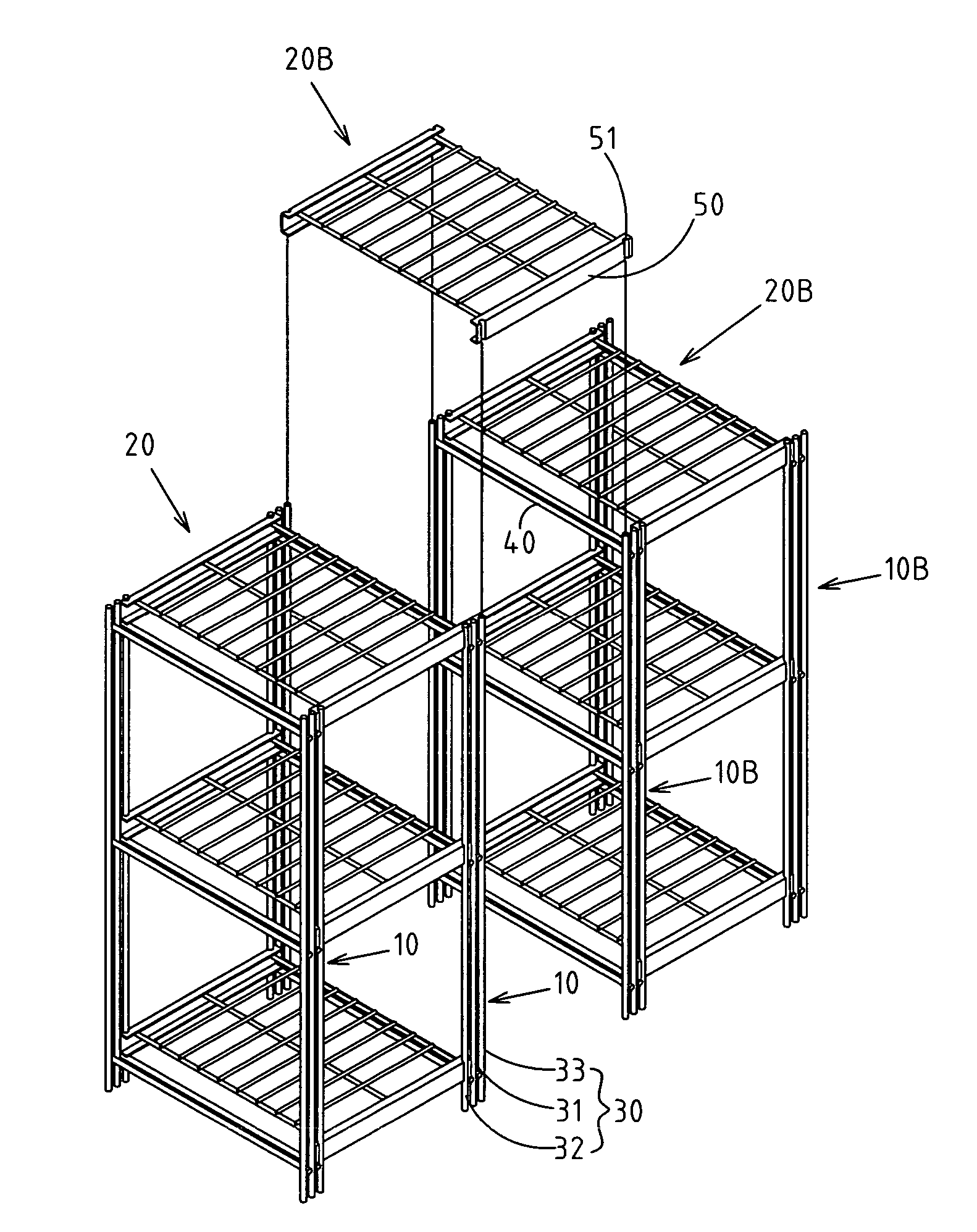
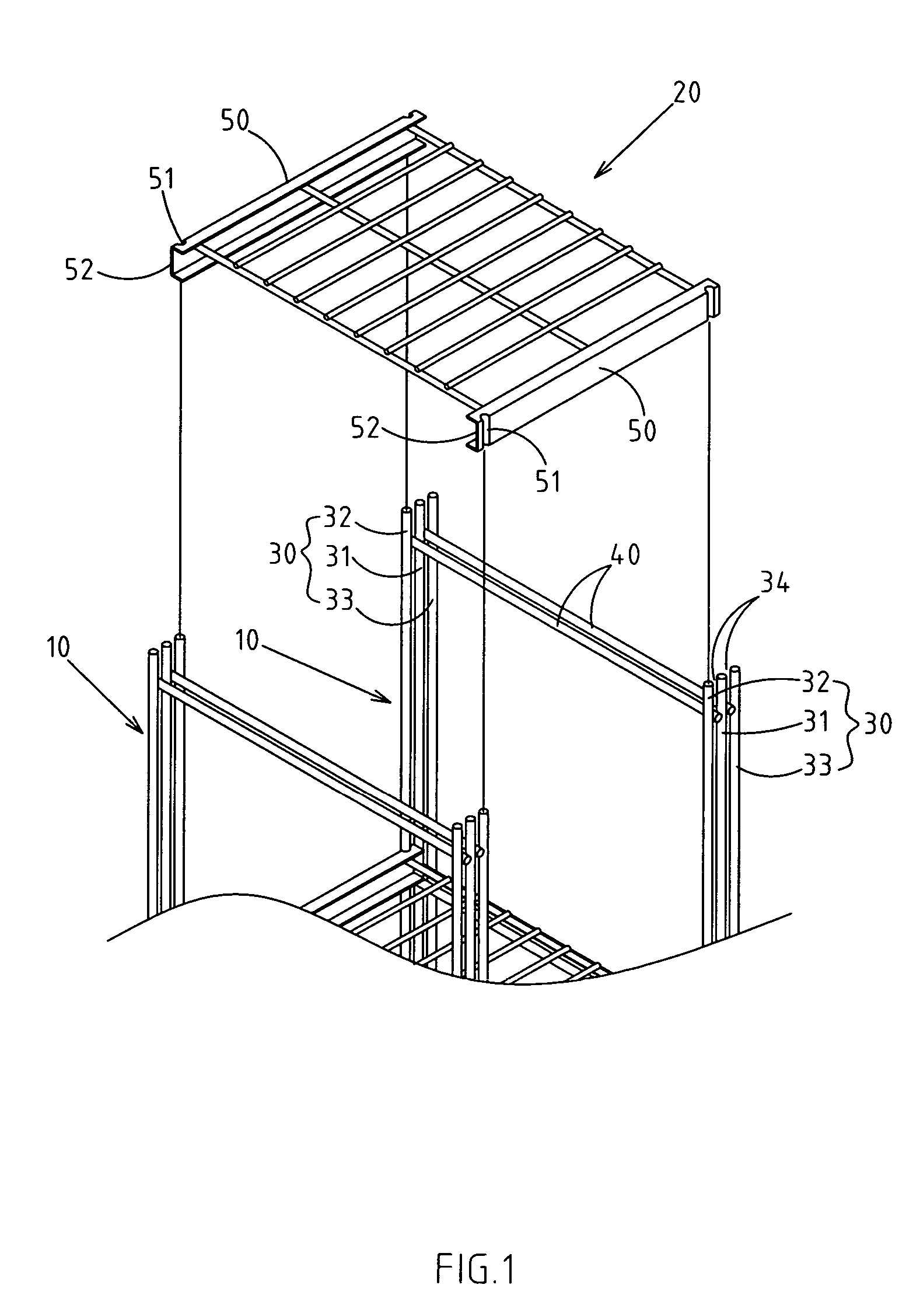
[0036] As shown in FIGS. 1-3, there is the first embodiment of the improved structure of assembled shelf. The main frame comprises two vertical side racks 10 and several sets of shelves 20. A shelf is placed between the two vertical side racks 10, and the fixed frame (connected by welding) is the vertical side rack made by a vertical bar 30 and horizontal bar 40. The horizontal bar 40 is placed on the pre-determined height of the shelf 20 for the shelf 20.

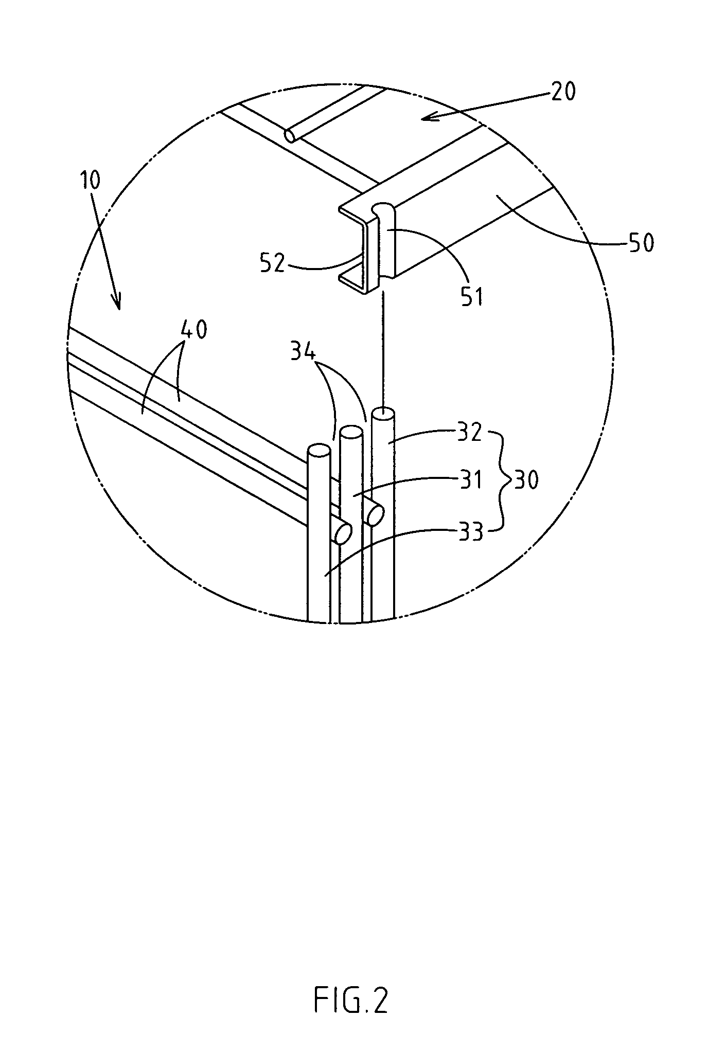
[0037] A vertical bar 30 of the vertical side rack 10 includes a main bar31 and an inner / outer secondary bar 3233. The inner / outer secondary bar is placed inside and outside of the main bar 31, and the main bar 31 is spaced between the inner / outer secondary bar 3233. The spa...


PUM


Abstract

The present invention provides an improved structure of the assembled shelf. The invention includes a main frame having two vertical side racks and several sets of shelves. Each shelf is placed inside the two vertical side racks. There is a vertical bar of the vertical side rack, which includes a main bar and at least one secondary bar. The secondary bar is placed on the sides of the main bar, and the space is formed by the distance of the horizontal bar. A frame is placed on both sides of the shelf, and a vertical groove is on both ends. The groove can be connected to the main and secondary bars. By so doing, each shelf and two vertical side racks do not have to use other components to be positioned and are compatible with a common extension, such as vertical side rack, to make the invention more practical.

Description

RELATED U.S. APPLICATIONS [0001] Not applicable. STATEMENT REGARDING FEDERALLY SPONSORED RESEARCH OR DEVELOPMENT [0002] Not applicable. REFERENCE TO MICROFICHE APPENDIX [0003] Not applicable. FIELD OF THE INVENTION [0004] The present invention relates generally to a structure of assembled shelf, and more particularly to a structure of an assembled shelf that has a vertical groove and bar to position the shelf and vertical side rack. BACKGROUND OF THE INVENTION [0005] Whether it is in a home or business place, an assembled shelf has importance, and through the deliberate efforts in the industry, it now has diversified structures. The current shelf can be divided into a one-piece structure and assembled structure. The main part of the one-piece structure is fixed; therefore, it cannot be taken apart. The main part of the assembled structure is made of the separated components (such as the shelf and side racks). Therefore, it can be taken apart and restored to its separated state. Curr...

Claims


Application Information

Patent Timeline
IPC IPC(8): A47B57/00A47B47/00A47B47/02
CPCA47B47/00A47B47/024
Inventor CHEN, HSIN-YUEH
Owner I JANG IND
Learn More