Encoding apparatus, encoding method, decoding apparatus, and decoding method

a technology of encoding apparatus and encoding method, which is applied in the direction of code conversion, color television with bandwidth reduction, television system, etc., can solve the problems of large code size generated, affecting the efficiency of encoding, and lowering the effect of improving encoding efficiency, so as to achieve the effect of reducing the number of frames and speeding up the motion compensation

Inactive Publication Date: 2007-05-17
CANON KK
View PDF19 Cites 18 Cited by
  • Summary
  • Abstract
  • Description
  • Claims
  • Application Information

AI Technical Summary

Benefits of technology

[0016] The present invention has been made in, consideration of the aforementioned problems, and has as its object to effectively reduce the number of frames to be referred to, and to perform an encoding process using faster motion compensation.

Problems solved by technology

However, when a change has occurred, a large code size is generated.
This poses a problem.
It lowers the effect of improving the encoding efficiency even when a plurality of frames are referenced.
The number of frames increases dramatically over a long period of time, the circuit scale becomes huge, and many additional processes are required, resulting in long processing times.

Method used


Image

  • Encoding apparatus, encoding method, decoding apparatus, and decoding method
  • Encoding apparatus, encoding method, decoding apparatus, and decoding method
  • Encoding apparatus, encoding method, decoding apparatus, and decoding method

Examples


first embodiment

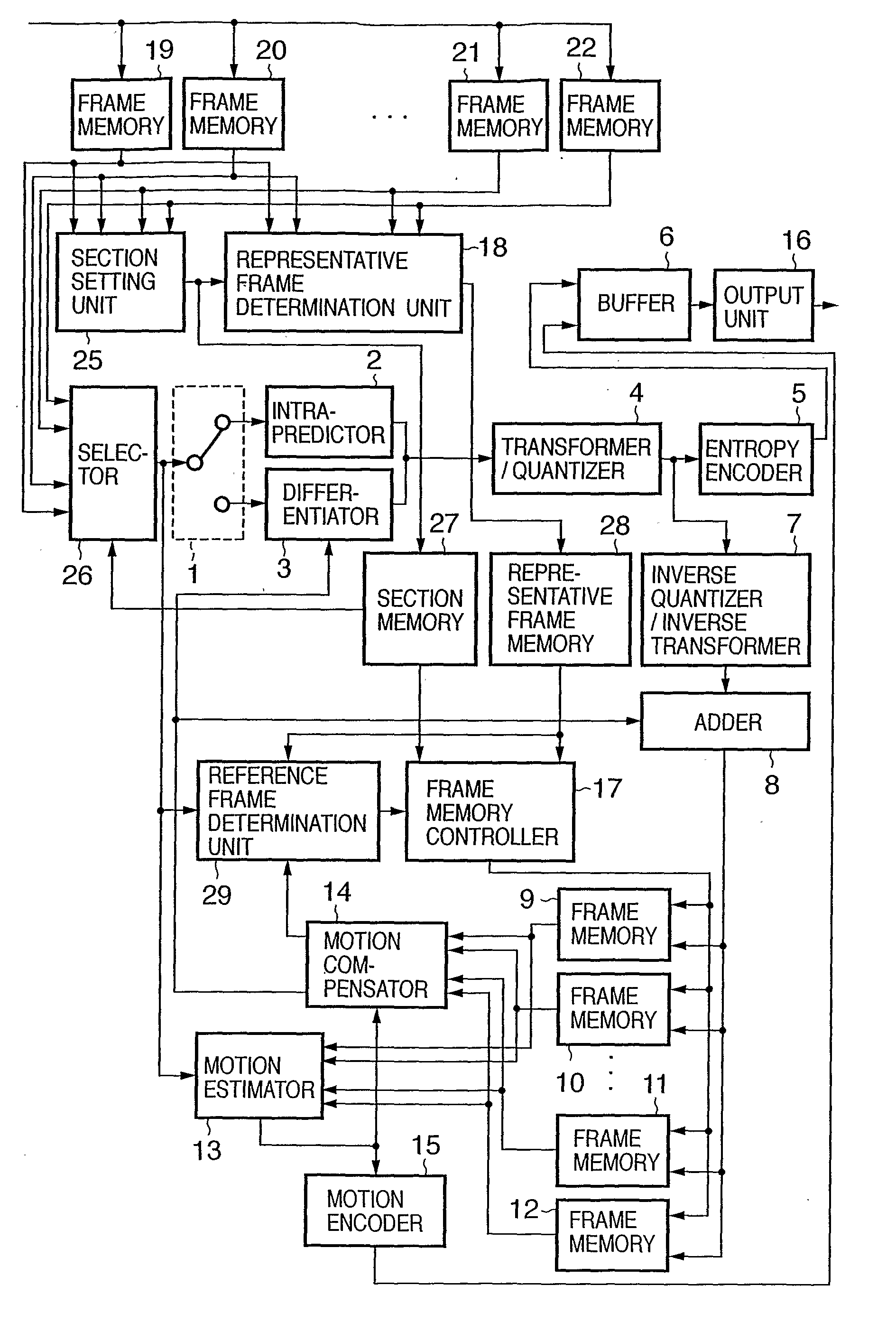
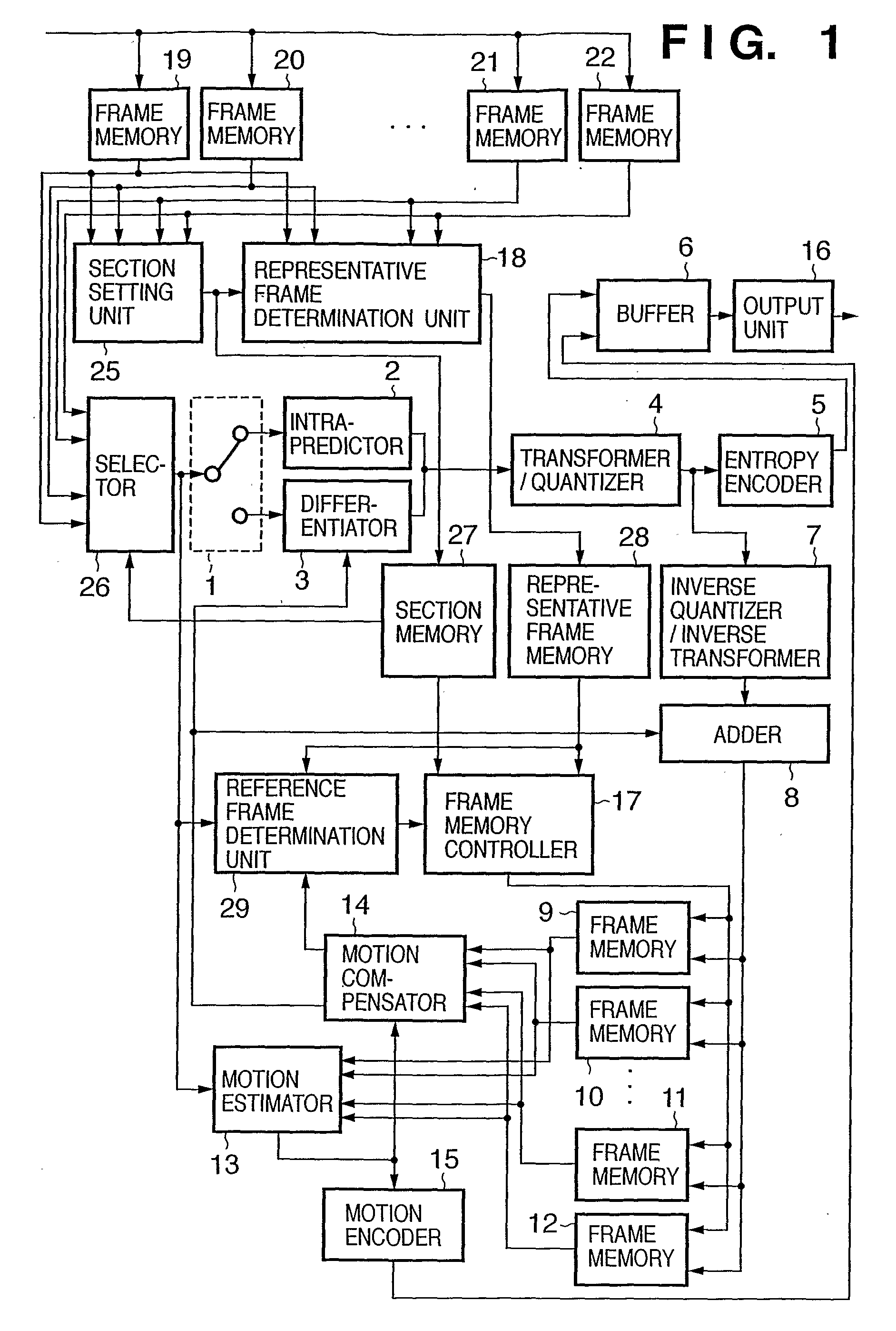
[0150]FIG. 1 is a block diagram showing the arrangement of a moving image encoding apparatus according to this embodiment. In this embodiment, a description will be given based on the H.264 encoding method, but temporally discontinuous reference frames are to be referred to unlike in H.264. However, the base method is not limited to H.264. For the sake of simplicity, forward prediction that refers to previous frames will be exemplified. However, the present invention can also be applied to two-way prediction. In the following description, image data of a frame will also be referred to as frame data. This frame data (an image of a frame) includes data indicating the frame number of this frame.

[0151] Referring to FIG. 1, reference numerals 19 to 22 denote frame memories for storing images of frames (input images) of an externally input moving image. Reference numeral 1 denotes a selector which selects an output destination in accordance with an intra-frame encoding / inter-frame encodi...

second embodiment

[0204]FIG. 3 is a block diagram showing the arrangement of a moving image encoding apparatus according to this embodiment. The same reference numerals in FIG. 3 denote the same parts as in FIG. 1, and a description thereof will be omitted.

[0205] Reference numeral 117 denotes a frame memory controller which controls inputs / outputs of the frame memories 9 to 12; and 125, a section setting unit which sets a section by calculating a similarity level upon comparison of input images. Reference numeral 118 denotes a representative frame determination unit which determines a representative frame that represents the section.

[0206] The moving image encoding process to be executed by the moving image encoding apparatus according to this embodiment will be described below.

[0207] As in the first embodiment, prior to encoding, the frame memories, section memory 27, and representative frame memory 28 are initialized. As an initialization process, each memory is padded with zero data.

[0208] In ...

third embodiment

[0247]FIG. 5 is a block diagram showing the basic arrangement of a moving image encoding apparatus according to this embodiment.

[0248] Referring to FIG. 5, reference numeral 300 denotes a CPU which controls the overall apparatus using programs and data loaded onto a memory 301 and executes respective processes to be described later. Reference numeral 301 denotes a memory which comprises an area for temporarily storing programs and data loaded from storage devices 304 and 305, and also a work area used when the CPU 300 executes respective processes.

[0249] Reference numeral 303 denotes a terminal which is used to input various settings, various instructions, and the like to the moving image encoding apparatus of this embodiment. Reference numeral 304 denotes a storage device which stores software programs for making the CPU 300 execute various processes, and data. Some or all of these software programs are loaded onto the memory 301 under the control of the CPU 300, and are to be pr...


PUM


Abstract

ABSTRACT Frames are divided into a plurality of sections on the basis of input images of the frames (S8). One representative image that represents the image of each frame is set in each of the sections (S10). One representative image to be referred to is selected so as to encode an image of a frame of interest from the representative images set for respective sections, and the image of the frame of interest is encoded by motion compensation using the images of the frames in the section that includes the selected representative image (S13, S14, S15).

Description

TECHNICAL FIELD [0001] The present invention relates to a technique for encoding frames that form a moving image by motion compensation, and a technique for decoding the encoded result. BACKGROUND ART [0002] In recent years the H.264 encoding method, as a new moving image encoding method, has received a lot of attention. This encoding method is jointly developed by the ITU-T and ISO. [0003] As a feature of this new encoding method, 4×4 integer transformation is used, and a plurality of intra-prediction schemes are prepared, unlike in the conventional MPEG-1, 2, and 4 encoding methods. An intra-loop filter is used, and motion compensation is made using seven different types of subblocks. The pixel precision of the motion compensation is as high as ¼ pixel precision as in the MPEG-4 encoding method. Furthermore, universal variable-length encoding and context adaptive variable-length encoding are used as entropy encoding. [0004] As a more significant feature, MPEG-1, 2, or 4 performs m...

Claims


Application Information

Patent Timeline
Patent Type & Authority Applications(United States)
IPC IPC(8): H04N11/02H04N19/50H03M7/36H04N19/102H04N19/105H04N19/12H04N19/134H04N19/137H04N19/154H04N19/172H04N19/196H04N19/51H04N19/523H04N19/57H04N19/58H04N19/60H04N19/91
CPCH04N19/139H04N19/172H04N19/61H04N19/58H04N19/137H04N19/573H04N19/107
Inventor MAEDA, MITSURU
Owner CANON KK
Why Eureka
Try Eureka