
Dynamic power allocation in system for providing power over communication link

a technology of communication link and power allocation, applied in the field of power supply system, can solve the problem of limited power available to support the operation of the pds

Inactive Publication Date: 2007-05-17
ANALOG DEVICES INT UNLTD
View PDF13 Cites 109 Cited by
  • Summary
  • Abstract
  • Description
  • Claims
  • Application Information

AI Technical Summary

Benefits of technology

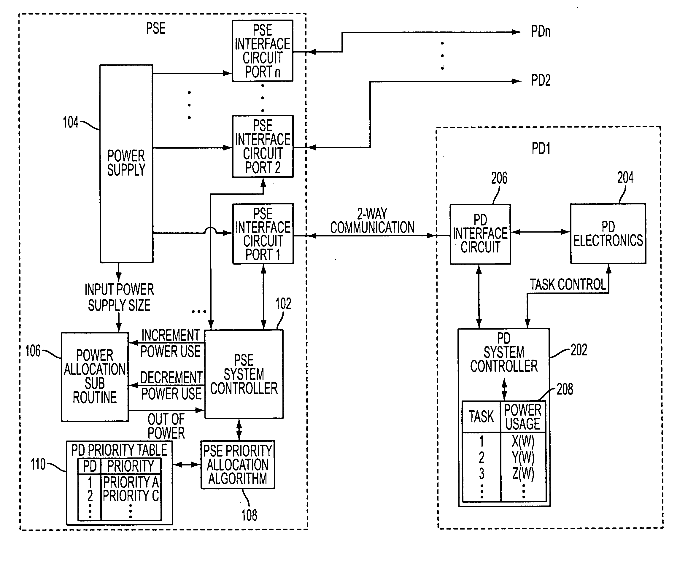
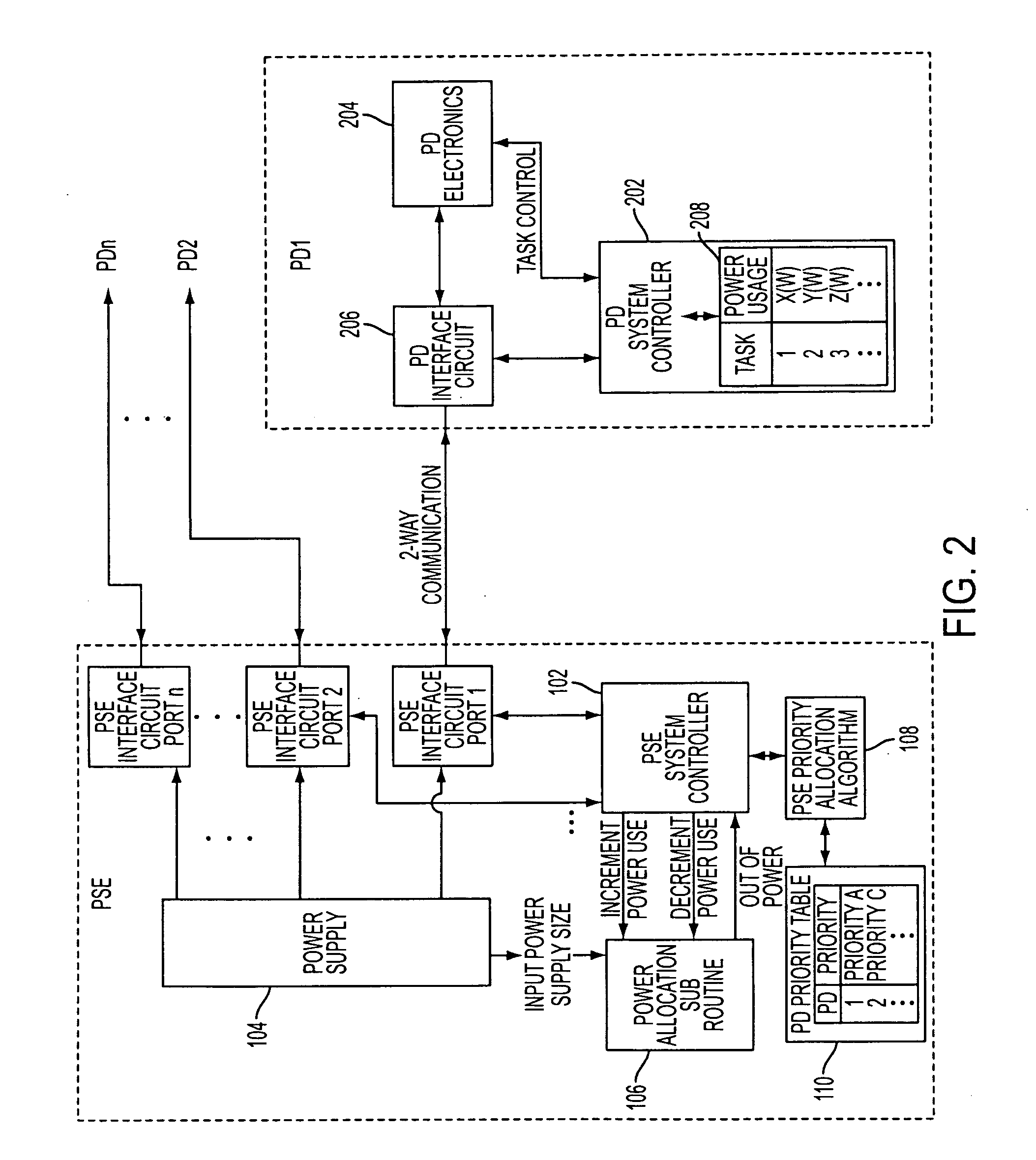
[0013] When the dynamic power allocation mechanism reduces or removes power allocated to a first PD, this power may be reallocated to a second PD. For example, the first PD may switch to a task associated with a lower power consumption, whereas the second PD switches to a task associated with a higher power consumption. Also, power may be reallocated from one PD to another if a power shortage is detected.
[0014] The system may further comprise a priority mechanism for assigning priorities to the PDs. The dynamic power allocation mechanism may reduce or remove power allocated to a lower-priority PD before reducing or removing power allocated to a higher-priority PD if a power shortage is detected.
[0015] Further, power allocated to a lower-priority PD may be reduced or removed to satisfy power demand from a higher-priority PD if a power shortage is detected.

Problems solved by technology

However, power available to support operations of the PDs is limited.
PSE will deny request for power from an additional PD if the available power is not sufficient to support its peak power usage.

Method used


Image

  • Dynamic power allocation in system for providing power over communication link
  • Dynamic power allocation in system for providing power over communication link
  • Dynamic power allocation in system for providing power over communication link

Examples


Embodiment Construction

[0029] The present disclosure will be made using the example of a power supply device in a PoE system. It will become apparent, however, that the concepts described herein are applicable to any power supply system. For example, the system of the present disclosure may be provided in a local area network (LAN) having a plurality of nodes, a network hub and communication cabling connecting the nodes to the network hub for providing data communications. The network hub may include a power supply device for providing power to a powered device over the communication cabling, and a dynamic power allocation mechanism of the present disclosure.

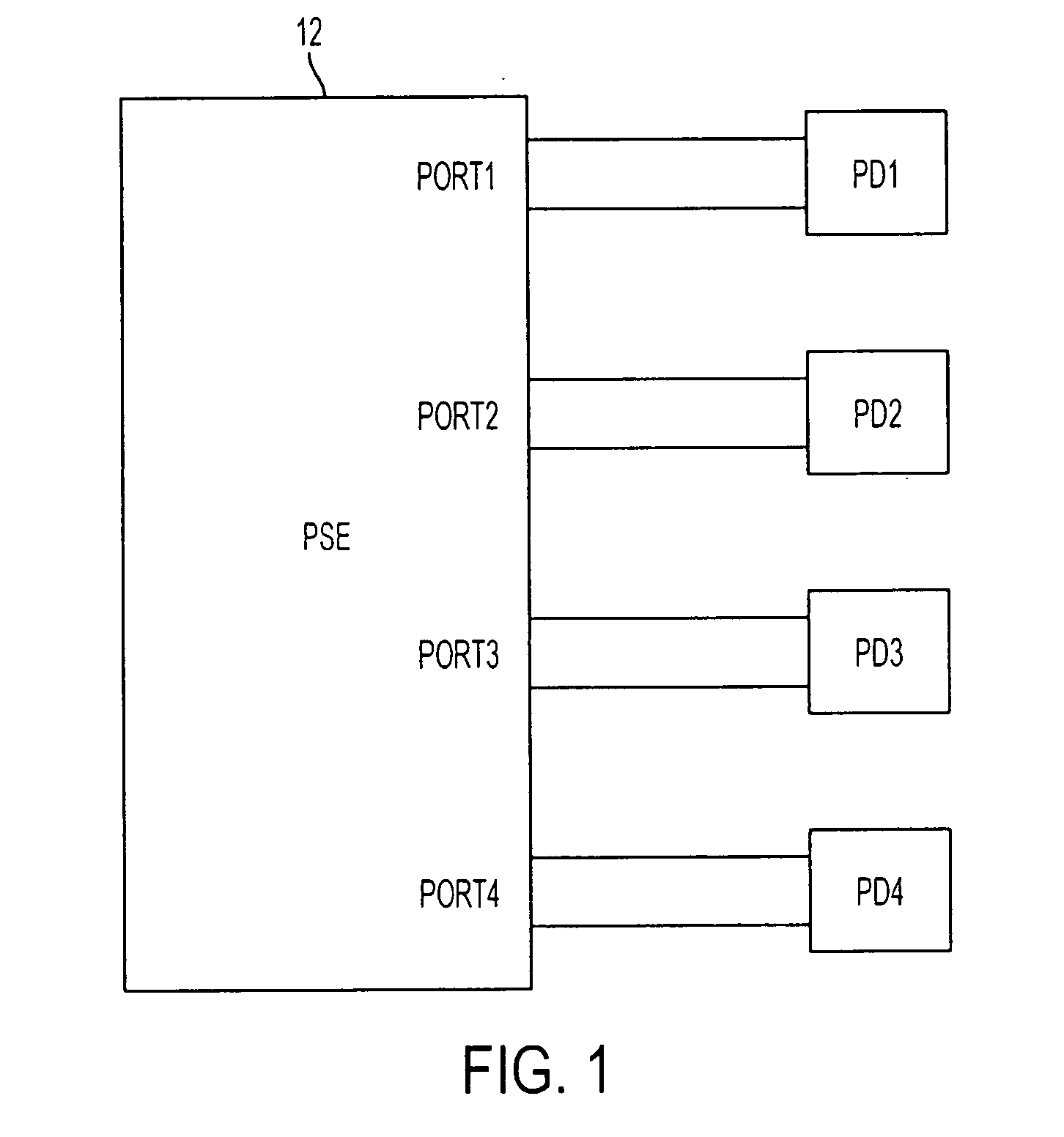
[0030]FIG. 1 shows a simplified block-diagram illustrating a Power over Ethernet (PoE) system 10 including Power Sourcing Equipment (PSE) 12 having multiple ports 1 to 4 connectable to Powered Devices (PD1 to PD4) via respective links, each of which may be provided using 2 or 4 sets of twisted pairs within an Ethernet cable. Although FIG. 1 shows fou...


PUM


Abstract

System and methodology for supplying power to a powered device (PD) over a communication link, such as an Ethernet link. The system has a power supply device that provides power to the PD, and a dynamic power allocation mechanism that dynamically modifies power allocated to the PD in accordance with tasks of the PD.

Description

[0001] This application claims priority of and incorporates by reference provisional U.S. patent application No. 60 / 736,328 filed on Nov. 15, 2005, and entitled “SYSTEM AND METHOD FOR SUPPORTING ADVANCED POWER OVER ETHERNET SYSTEM.”TECHNICAL FIELD [0002] This disclosure relates to power supply systems, and more particularly, to circuitry and methodology for performing dynamic power allocation in a system for providing power over a communication link, such as a Power over Ethernet (PoE) system. BACKGROUND ART [0003] Over the years, Ethernet has become the most commonly used method for local area networking. The IEEE 802.3 group, the originator of the Ethernet standard, has developed an extension to the standard, known as IEEE 802.3af, that defines supplying power over Ethernet cabling. The IEEE 802.3af standard defines a Power over Ethernet (PoE) system that involves delivering power over unshielded twisted-pair wiring from a Power Sourcing Equipment (PSE) to a Powered Device (PD) lo...

Claims


Application Information

Patent Timeline
Patent Type & Authority Applications(United States)
IPC IPC(8): G02B6/12
CPCH04L12/10H04L41/0803H04L49/40
Inventor STANFORD, CLAYTON REYNOLDS
Owner ANALOG DEVICES INT UNLTD
Learn More