Mattress pad

a mattress pad and mattress technology, applied in the field of therapeutic body support pads, can solve the problems of commercially impractical to accommodate the mass media's need, and achieve the effect of slow recovery and enhanced comfor

Active Publication Date: 2007-05-24
OPRANDI ARTHUR V
View PDF53 Cites 9 Cited by
  • Summary
  • Abstract
  • Description
  • Claims
  • Application Information

AI Technical Summary

Benefits of technology

[0033] This invention is directed to a mattress pad positionable atop a rectangular mattress for accommodation of the diverse weight and sizes of the human anatomy for enhanced comfort. The mattress pad in one embodiment includes a flexible bottom sheet having a size and shape substantially similar to that of a top surface of the mattress. A flexible fabric top sheet is preferably connected to the bottom sheet by peripheral stitching along common perimeter side, head and foot margins. A plurality of generally side-by-side body supporting members are each defined by peripheral stitching and spaced lines of continuous stitching which interconnect said top and bottom sheets. Each body supporting member is filled with a resilient, compressible, substantially homogeneous or uniform closed or open cell urethane or polyurethane foam, preferably a viscoelastic polyurethane foam having slow recovery characteristics, a / k / a memory foam. In another embodiment, the mattress top pad is mold formed as a unit of viscoelastic polyurethane such as a memory foam molded in one piece. Preselected thicknesses of each of the body support members provide the comfort and accommodation to each of the portions of the human anatomy.
[0034] It is therefore an object of this invention to provide a mattress pad which is positionable atop a conventional mattress which will greatly enhance the comfort and accommodation to individualized body sizes, shapes and weights of each person on an individual basis.
[0035] Still another object of this invention is to provide a mattress pad having chambers filled with viscoelastic slow recovery memory foam to enhance the comfort level of a person lying recumbent thereupon.

Problems solved by technology

Although it is well known that the comfort level is heightened to the extent that the mattress conforms to the individual curves of the human anatomy, nonetheless it is commercially impractical to accommodate this need for the mass media.

Method used


Image

  • Mattress pad
  • Mattress pad
  • Mattress pad

Examples


embodiment 10

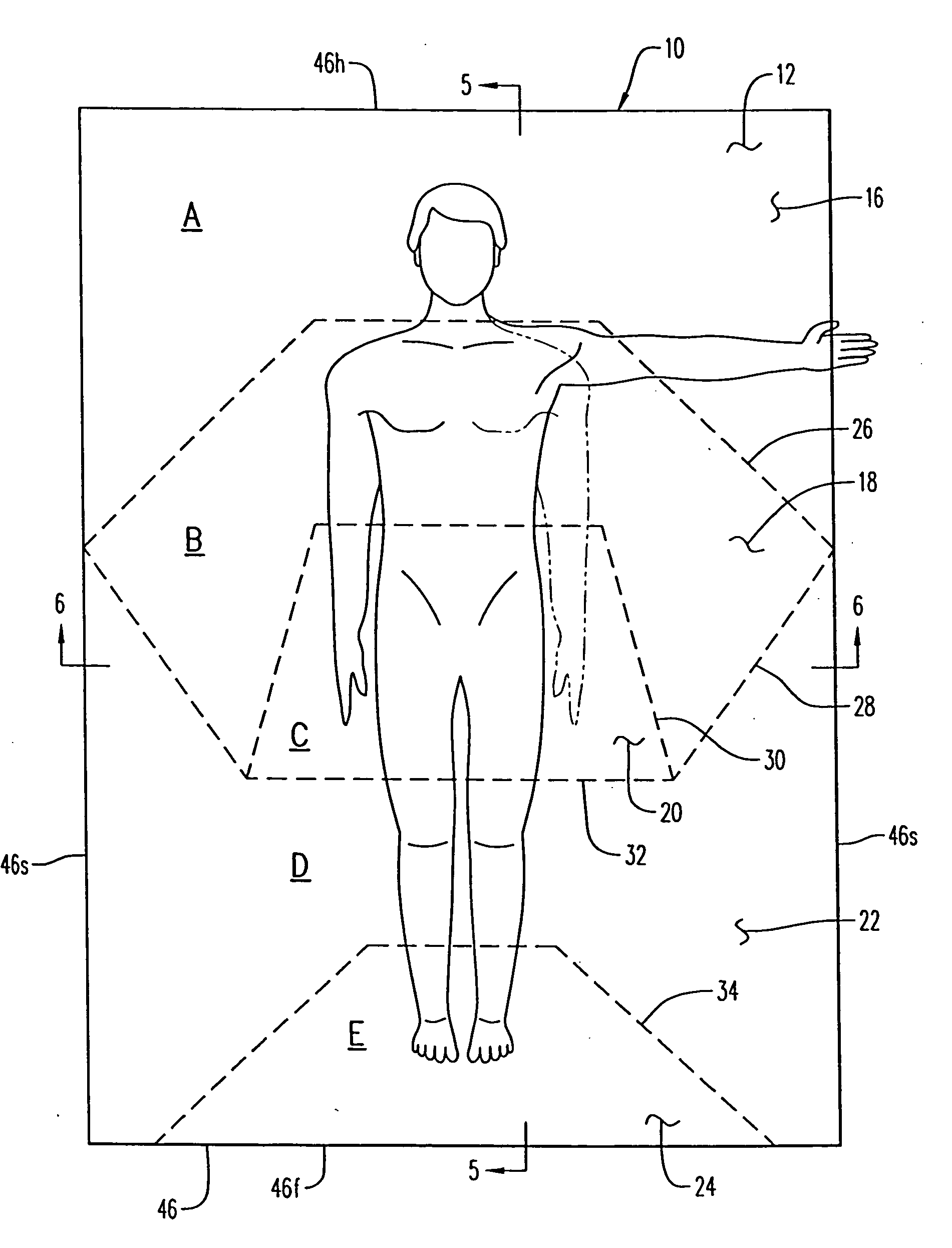
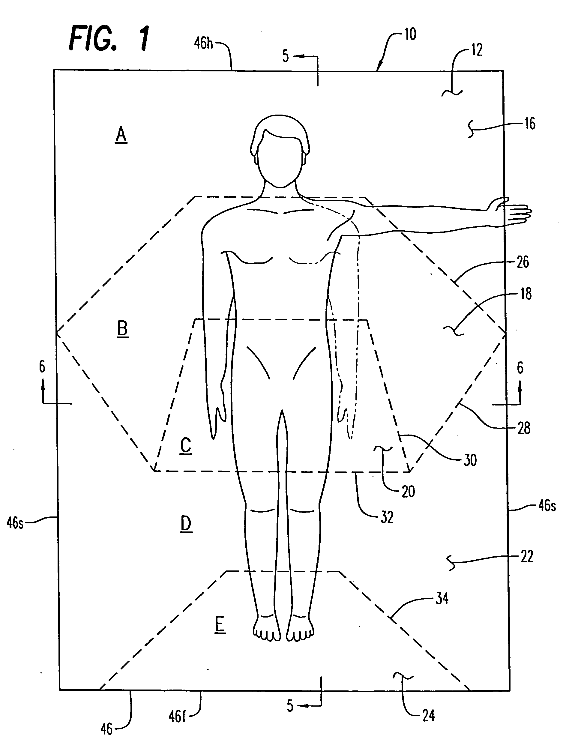
[0054] Referring now to the drawings, and firstly to FIGS. 1 and 3 to 8, one embodiment of the invention is there shown generally at numeral 10 and includes a flexible, substantially rectangular fabric top sheet 12 and a flexible bottom sheet 14 which are stitched together along common head, foot and side margins shown generally at numeral 46 and as detailed in FIG. 7. Material selection in forming the top and bottom sheets includes flexible sheet cotton, wool, linen, plastic, latex and all other organic or synthetic flexible sheet materials. Within the rectangular perimeter borders 46 of this mattress pad 10 are formed a plurality of spaced lines of continuous intermediate stitching referred to generally at 26, 28, 30, 32 and 34. In this embodiment 10, these stitching lines are straight for manufacturing convenience.

[0055] Intermediate stitch line 26 has a generally transverse central component and downwardly descending diagonal components which define a first chamber 16 between th...

embodiment 80

[0063] Referring now to FIGS. 10 and 11, a queen or king-size embodiment is there shown generally at numeral 80 to accommodate two recumbent persons in side-by-side fashion in a conventional double bed arrangement. In this embodiment 80, two separate chamber supported areas 84 and 86 are provided as defined by a longitudinally extending stitch line 102 which is positioned centrally between the periphery side margins of the mattress pad 80.

[0064] Again, in this embodiment 80, a head chamber 88, a shoulder chamber 90, a mid-torso chamber 92, a lower torso chamber 94, an upper leg chamber 96, a lower leg chamber 98, and a foot chamber 100 are provided by parallel transverse intermediate stitching lines shown typically at 104.

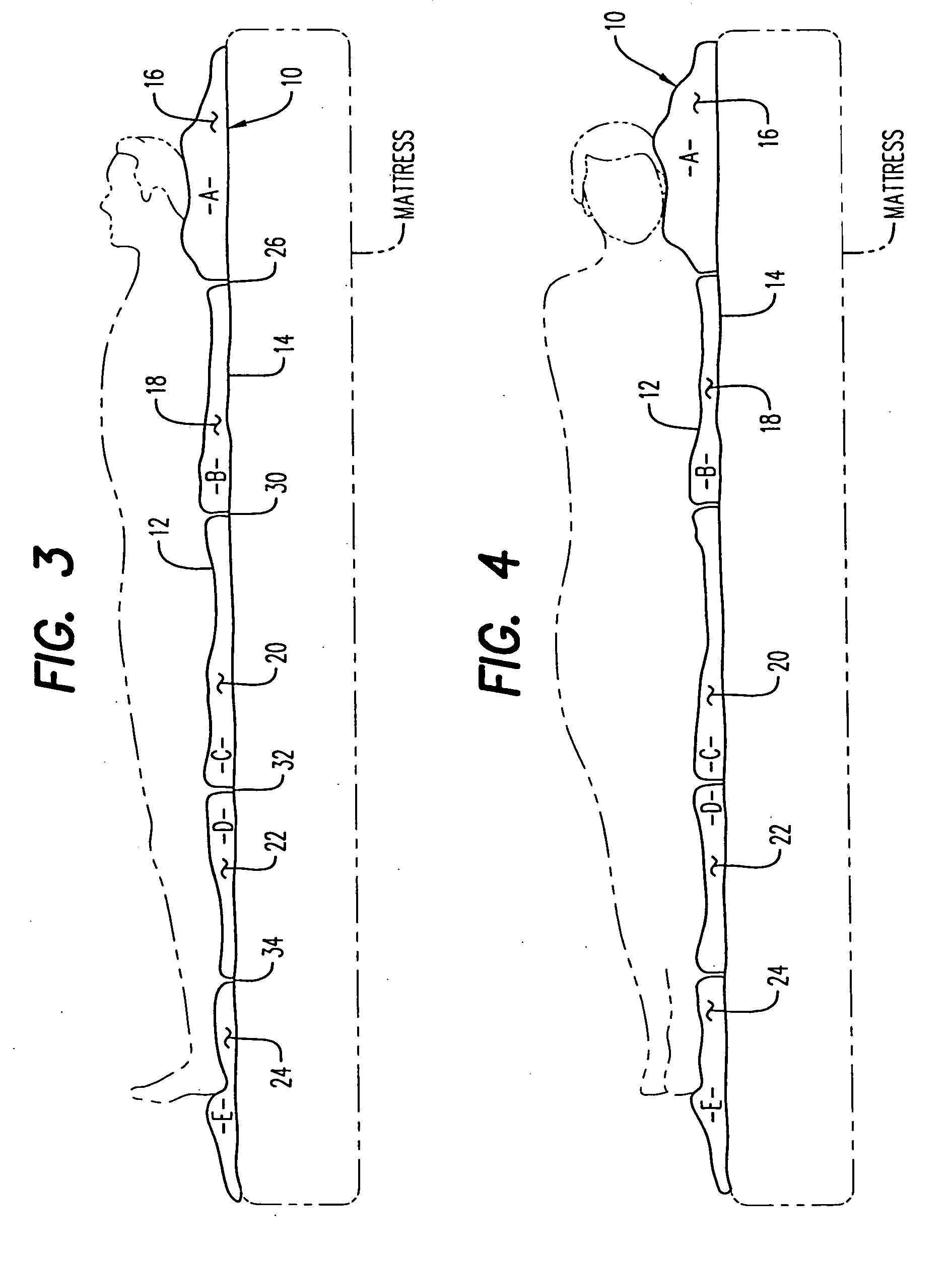
[0065] The height of the foam material filling each of these chambers, 88, 90, 92, 94, 96, 98, and 100 is the same as referenced in FIG. 1 wherein height A is the thickest of the foam material to support the head and neck. Chambers 90 and 92 are separated by a lin...

embodiment 130

[0067] The embodiment 130 shown in FIG. 13 includes a flexible fabric top sheet 132 having intermediate stitching shown typically at 144 passing through both the top sheet 132 and the bottom sheet (not shown) as previously described. This embodiment 130 includes a head support chamber 134 having components 134a, 134b and 134c, chamber 134a being of sufficient length and centrally positioned to support both the head, neck and upper shoulders area of a recumbent person. Narrower chamber 136 and its individual chamber components 136a, 136b and 136c, serve to support the center torso and arms of the user, while chamber 138 having central and side component chambers 134a and 134b and 134c, respectively, support the lower torso and upper leg area of the person. Central chamber 140a of chamber 140 supports the lower leg area, and finally central chamber 142a of chamber 142 supports the feet of the user. Chambers 140b and 140c and 142b and 142c serve to primarily control foam material migra...


PUM


Abstract

A mattress pad positionable atop a rectangular mattress which better accommodates diverse weights and sizes of the human anatomy for enhanced comfort. The mattress pad includes a flexible bottom sheet having a size and shape substantially similar to that of a top surface of the mattress. A flexible fabric top sheet is connected to the bottom sheet by peripheral stitching along common perimeter side, head and foot margins. A plurality of generally side-by-side body supporting chambers are each defined by peripheral stitching and spaced lines of continuous stitching which interconnect the top and bottom sheets. Each chamber is filled with an open or closed cell urethane foam material. Preselected nominal thicknesses of each of the chambers provides the comfort and accommodation to each portion of the human anatomy.

Description

CROSS-REFERENCE TO RELATED APPLICATIONS [0001] Not applicable STATEMENT REGARDING FEDERALLY SPONSORED RESEARCH OR DEVELOPMENT [0002] Not applicable INCORPORATION-BY-REFERENCE OF MATERIAL SUBMITTED ON A COMPACT DISC [0003] Not applicable BACKGROUND OF THE INVENTION [0004] 1. Field of the Invention [0005] This invention relates generally to therapeutic body support pads and more particularly to an anatomically conformable mattress pad or overlay positionable atop a conventional mattress for enhanced body comfort for a recumbent person. [0006] 2. Description of Related Art [0007] Conventional mattresses are typically designed for the general public or typical users to provide a reasonable degree of comfort to a broad base range of people. Although it is well known that the comfort level is heightened to the extent that the mattress conforms to the individual curves of the human anatomy, nonetheless it is commercially impractical to accommodate this need for the mass media. [0008] A num...

Claims


Application Information

Patent Timeline
Patent Type & Authority Applications(United States)
IPC IPC(8): A47C27/14
CPCA47C27/082A47C27/087A47C27/10A47C27/146A47C27/148
Inventor OPRANDI, ARTHUR V.
Owner OPRANDI ARTHUR V
Why Eureka
Try Eureka