Method and apparatus for alignment of firearm sights

a sighting device and alignment method technology, applied in the direction of sighting devices, weapons, weapon components, etc., can solve the problems of time-consuming and labor-intensive external vertical reference lines and visual alignment of reference lines with vertical crosshairs of sighting devices, and achieve the effect of reducing time needed and being convenient to use and manufactur

Inactive Publication Date: 2007-05-24
BATTENFELD TECH
View PDF99 Cites 83 Cited by
  • Summary
  • Abstract
  • Description
  • Claims
  • Application Information

AI Technical Summary

Benefits of technology

[0007] Among the several objects of the invention may be noted the provision of an apparatus for aligning a sighting device with a firearm, the provision of such an apparatus that reduces the time needed to accurately align the sighting device with the firearm, and the provision of such an apparatus that is easy to use and manufacture.

Problems solved by technology

If a sight is rotationally misaligned the shooters ability to accurately fire the firearm will be compromised.
If the sight is misaligned, movement that appears to be truly horizontal, as viewed through the sight, will also affect the vertical placement of the projectile.
The creation of an external vertical reference line and visual alignment of the reference line with the vertical crosshair of the sighting device are time consuming and require precision in checking that the external reference is truly vertical and perfectly aligned with the vertical crosshair.
Further, a fixed external reference line is difficult to establish in some shooting environments (e.g., uneven terrain or high wind conditions).
Currently there are no commercially available devices that provide quick and accurate alignment of the sighting device and the firearm.

Method used


Image

  • Method and apparatus for alignment of firearm sights
  • Method and apparatus for alignment of firearm sights
  • Method and apparatus for alignment of firearm sights

Examples


Embodiment Construction

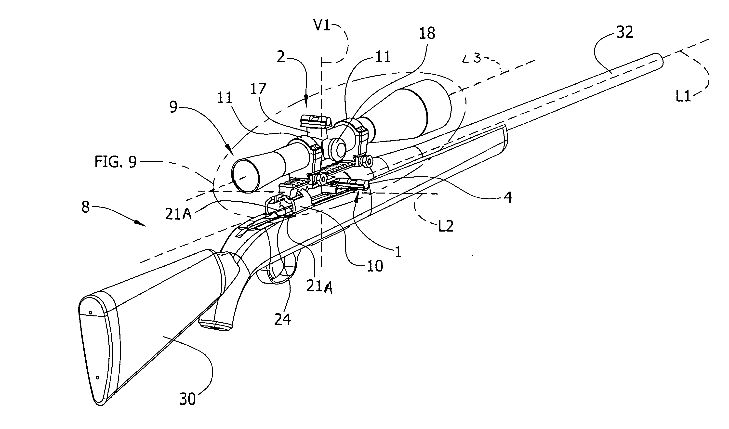
[0023] As shown in FIGS. 8 and 9, the present invention serves as an aid for mounting a sighting device or sight, generally designated 9, on a firearm, generally designated 8. The present invention comprises a first level (firearm level) 1 removably attached to the firearm 8 and a second level (sight level) 2 removably mounted on the sighting device 9. In the illustrated embodiment, the sighting device 9 is a telescopic scope but it will be understood that the sighting device may be any other device for improving the accuracy of the firearm 8 such as a receiver sight, or an open sight.

[0024] In the illustrated embodiment, the firearm 8 is a conventional bolt-action rifle, but it will be understood that the present invention may be used to align a sighting device 9 attached to other types of firearms. As shown in FIGS. 5-7, the rifle 8 comprises a stock 30, a receiver 10 attached to the stock, and a barrel 32 threadably attached to the receiver. The rifle 8 has a central longitudina...


PUM


Abstract

An apparatus for aligning a sighting device mounted on a firearm. The apparatus has a first indicating device adapted to be positioned on a surface of the firearm to determine a rotational position of the firearm relative to a reference plane and a second indicating device adapted to be positioned on a surface of the sighting device to determine a rotational position of the sighting device relative to the reference plane.

Description

CROSS-REFERENCE TO RELATED APPLICATION [0001] This application is a non-provisional of U.S. Provisional Patent Application Ser. No. 60 / 602,768, filed Aug. 18, 2004, which is incorporated herein by reference.BACKGROUND OF THE INVENTION [0002] This invention relates generally to an apparatus for aligning a sighting device on a firearm, and more particularly to an apparatus for rotationally aligning the sighting device with a horizontal plane. [0003] A sight or sighting device is designed to enable the firearm user to accurately locate a projectile (e.g., bullet) at a precise point on a target. Typical sights have a horizontal crosshair and a vertical crosshair that assist the shooter in accurately aiming the firearm. The sight allows the shooter to precisely adjust or move the point of impact of the projectile on the target as necessary. Some examples of typical sights used on firearms include telescopic sights, receiver sights, and open sights. The discussion of firearms will pertain...

Claims


Application Information

Patent Timeline
Patent Type & Authority Applications(United States)
IPC IPC(8): F41G1/38
CPCF41G1/44
Inventor POTTERFIELD, RUSSELL A.COFFIELD, ORUS REID III
Owner BATTENFELD TECH
Why Eureka
Try Eureka