
Isolation system for an inertial measurement unit

a technology of inertial measurement and isolation system, which is applied in the direction of mechanical equipment, turn-sensitive devices, instruments, etc., can solve the problem that elastomers cannot be placed between at least one side surface, and achieve the effect of increasing the attenuation of shock and vibration energy

Inactive Publication Date: 2007-05-24
HONEYWELL INT INC
View PDF53 Cites 41 Cited by
  • Summary
  • Abstract
  • Description
  • Claims
  • Application Information

AI Technical Summary

Benefits of technology

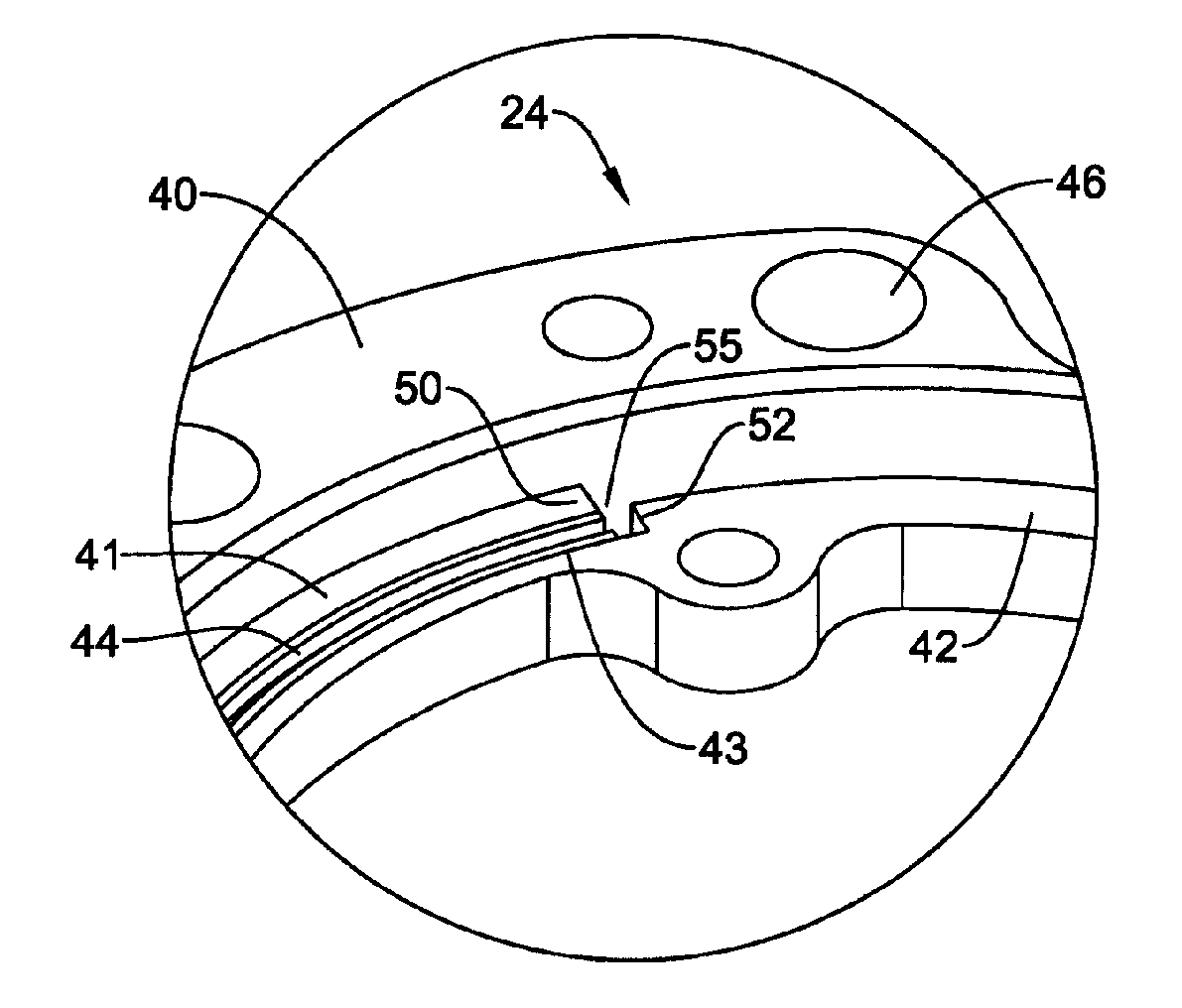
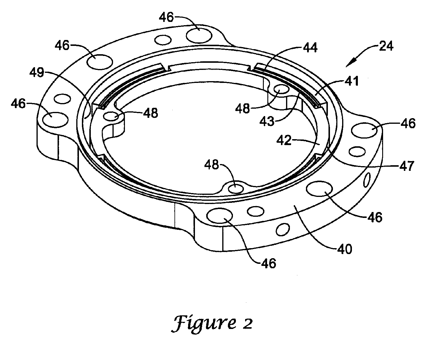
[0005] The present invention relates generally to inertial measurement units (IMUs) and more particularly to attenuating shock and vibrational energy using an IMU isolator. In one illustrative embodiment, an inertial measurement unit (IMU) having an isolator includes an outer ring having an inner surface with a protruding portion and an inner ring having an outer surface adjacent the inner surface of the outer ring, the outer surface having an recessed portion. The protruding portion is positioned at least partially within the recessed portion and may be interlocking to prevent excessive rotation of the inner ring relative to the outer ring when the IMU experiences a high rotational force. Furthermore, the illustrative IMU may include a sensor suite attached to the inner ring, the sensor suite having at least one inertial sensor, and a cover member and a base member attached to the outer ring forming a cavity for the sensor suite, the cavity defined by cavity walls.
[0006] Additionally, an elastomer may be positioned between at least a portion of the outer ring and at least a portion of the inner ring to help increase attenuation of shock and vibrational energy in the sensor suite. In some cases, the elastomer may be positioned between at least one side surface of the recessed portion and at least one side surface of the protruding portion. However, in other cases, the elastomer may not be positioned between at least one side surface of the recessed portion and at least one side surface of the protruding portion.
[0009] In another illustrative embodiment, an inertial measurement unit (IMU) having an isolator includes an outer ring having an inner surface with a recessed portion and an inner ring having an outer surface adjacent the inner surface of the outer ring, the outer surface having an protruding portion. The protruding portion may be interlocked with the recessed portion by positioning the protruding portion at least partially within the recessed portion to prevent excessive rotation of the inner ring relative to the outer ring when a rotational force is experienced. Additionally, an elastomer may be positioned between at least a portion of the outer ring and at least a portion of the inner ring.

Problems solved by technology

However, such extremely high dynamic environments demand a smaller, lighter, and more durable mechanism to withstand the high acceleration, such as 20,000 g's, associated with these environments.
However, in other cases, the elastomer may not be positioned between at least one side surface of the recessed portion and at least one side surface of the protruding portion.

Method used


Image

  • Isolation system for an inertial measurement unit
  • Isolation system for an inertial measurement unit
  • Isolation system for an inertial measurement unit

Examples


Embodiment Construction

[0017] The following description should be read with reference to the drawings wherein like reference numerals indicate like elements throughout the several views. The detailed description and drawings show several embodiments which are meant to be illustrative of the claimed invention.

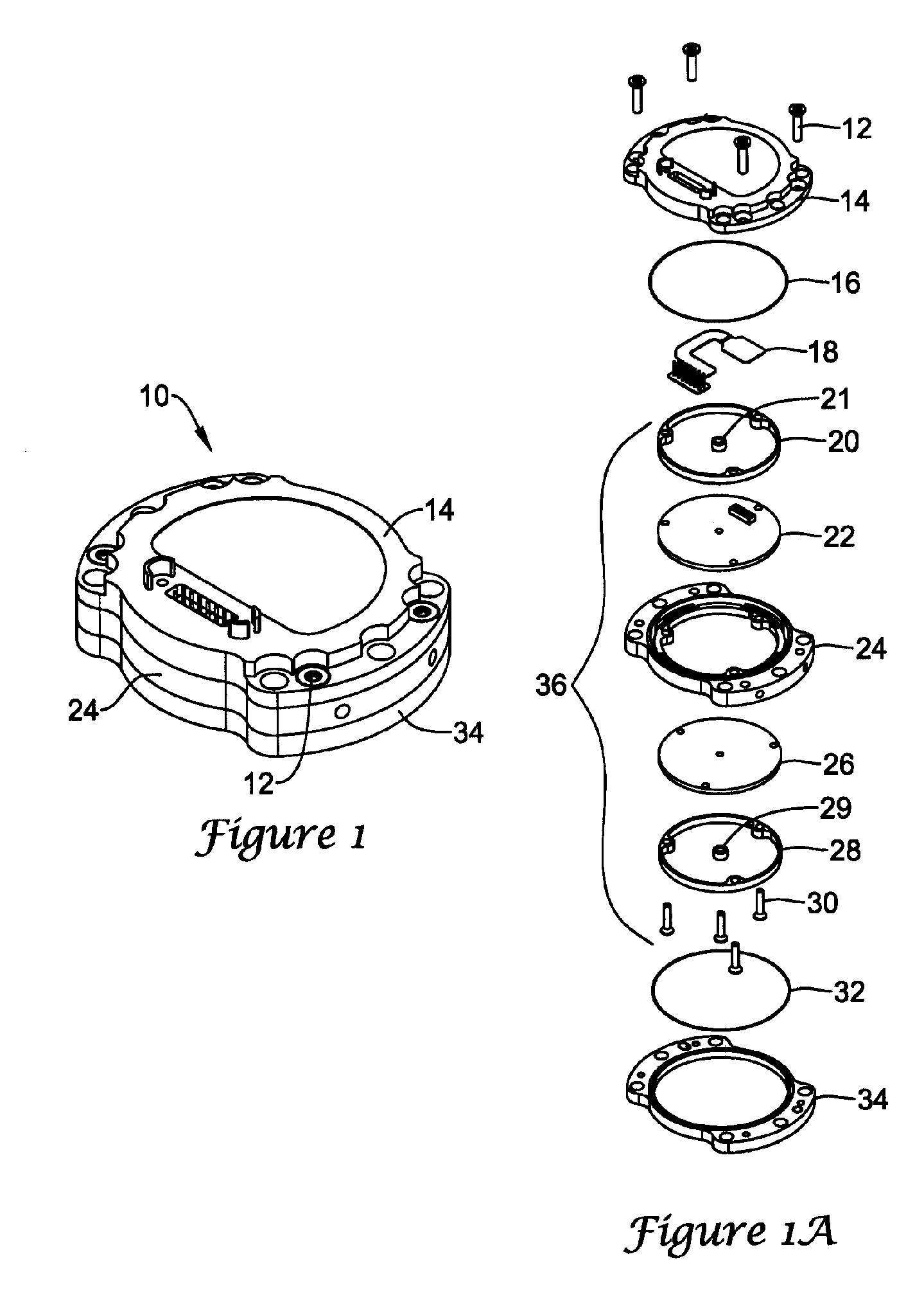
[0018]FIG. 1 is a perspective view of an illustrative inertial measurement unit (IMU) 10 in accordance with the present invention. The illustrative IMU 10 is designed to help decrease the shock, vibrational, and / or acoustic energy transmitted to the inertial sensors contained in the IMU 10 and may include self-snubbing features when exposed to high dynamic environments, including, for example, gun launches greater than 20,000 g's, to protect the inertial sensors. Additionally, the illustrative IMU 10 may be able to withstand higher g-forces than conventional IMUs due to its smaller and lighter weight design. That is, the forces realized on the IMU is directly related to the mass of the IMU, thus the ...


PUM


Abstract

In one illustrative embodiment, an isolator for an inertial measurement unit (IMU) is provided that includes an inner ring with an outer surface and an outer ring with an inner surface. The inner ring of the isolator may have a recessed portion and the outer ring may have a protruding portion, wherein the protruding portion is interlocked with at least part of the recessed portion to prevent excessive rotation of the inner ring relative to the outer ring during high rotational events. The isolator may also include an elastomer position between at least a portion of the inner ring and at least a portion of the outer ring to provide enhanced vibration and / or shock isolation during operation of the IMU, and to provide dampening of shock events during bottoming out of isolator during high shock events.

Description

FIELD [0001] The present invention relates generally to inertial measurement units (IMUs) and more particularly to attenuating shock and vibrational energy using an IMU isolator. BACKGROUND [0002] In certain environments, it may be necessary to isolate mechanically sensitive assemblies from shock, vibrational, and acoustic energy. In many applications, this may be accomplished by placing the sensitive components within some form of container or housing. The need to isolate a device from shock, vibrational, and / or acoustic energy may be particularly acute when the device is an inertial sensor assembly (ISA), which may include a sensor suite of an inertial measurement unit (IMU). An ISA typically includes inertial sensors that detect acceleration and / or rotation in three axes. Usually, three accelerometers and three rotational rate sensors are arranged with their input axes in a perpendicular relationship. The sensors may generally be rigidly and precisely mounted within an ISA housin...

Claims


Application Information

Patent Timeline
Patent Type & Authority Applications(United States)
IPC IPC(8): F16F15/12
CPCF16F15/08F16F15/126Y10T74/2131G01C21/16G01P1/023G01C19/56
Inventor BRAMAN, TODD L.HAGENSON, DALE J.
Owner HONEYWELL INT INC
Learn More