Eureka AIR delivers breakthrough ideas for toughest innovation challenges, trusted by R&D personnel around the world.

Cutting fixture for printed circuit board mounted with electronic components

Inactive Publication Date: 2007-05-24
INVENTEC CORP
View PDF14 Cites 17 Cited by
  • Summary
  • Abstract
  • Description
  • Claims
  • Application Information

AI Technical Summary

Benefits of technology

[0008] According to the above defects, an objective of the present invention is to provide a cutting fixture for a printed circuit board mounted with electronic components, which can effectively fix the printed circuit board to the cutting fixture so as to prevent the displacement of the cutting position of the printed circuit board.
[0009] Another objective of the present invention is to provide a cutting fixture for a printed circuit board mounted with electronic components, through which a printed circuit board mounted with electronic components can be easily attached to or detached from the cutting fixture, thereby increasing the cutting efficiency.
[0010] A further objective of the present invention is to provide a cutting fixture for a printed circuit board mounted with electronic components, which can efficiently prevent cutting errors, thereby increasing the production yield.

Problems solved by technology

Although the above positioning pins can be inserted into different positioning holes according to different types of printed circuit board modules, it may take as much as 2 hours to rearrange the positioning pins to make them correspond in position to a new type of printed circuit board modules in practical fabrication processes, thereby adversely affecting the cutting efficiency.
In addition, since the distance between the adjacent positioning holes arranged on the grid-shaped plate is certain and can not be changed, it is almost impossible to completely align the positioning pins with the predefined openings of the printed circuit board module, which not only makes it difficult to fix the printed circuit board module to the cutting fixture, but also leads to too loose or too tight engagement between the positioning pins and the openings.
Too loose engagement between the positioning pins and the openings causes the printed circuit board module to displace during the cutting process, while too tight engagement between the positioning pins and the openings increases difficulty of detachment of the printed circuit board module from the cutting fixture and causes the printed circuit board module to tilt during the cutting process.
Displacing and tilting of the printed circuit board module are easy to introduce the cutting error during the cutting process, which adversely affects the cutting quality.

Method used


Image

  • Cutting fixture for printed circuit board mounted with electronic components
  • Cutting fixture for printed circuit board mounted with electronic components
  • Cutting fixture for printed circuit board mounted with electronic components

Examples


Embodiment Construction

[0021] Hereunder, embodiments of the present invention will be described in full detail with reference to the accompanying drawings.

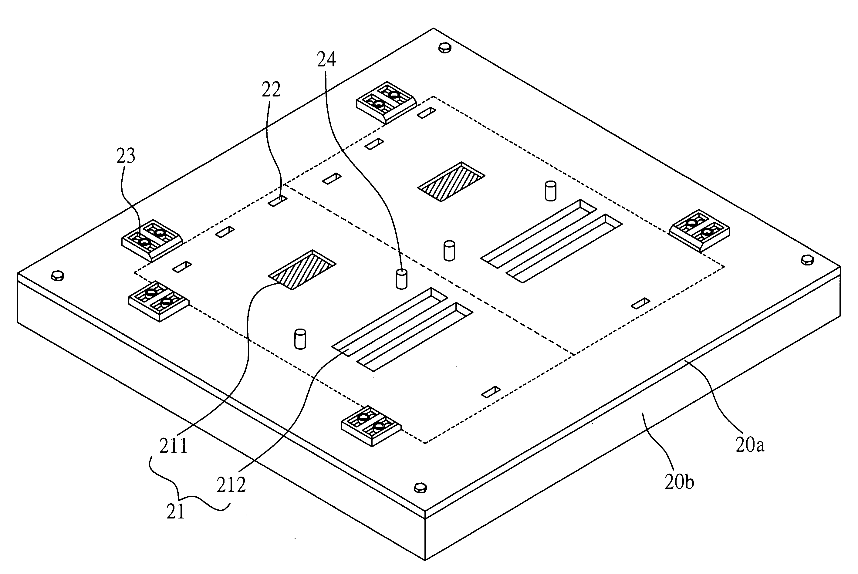
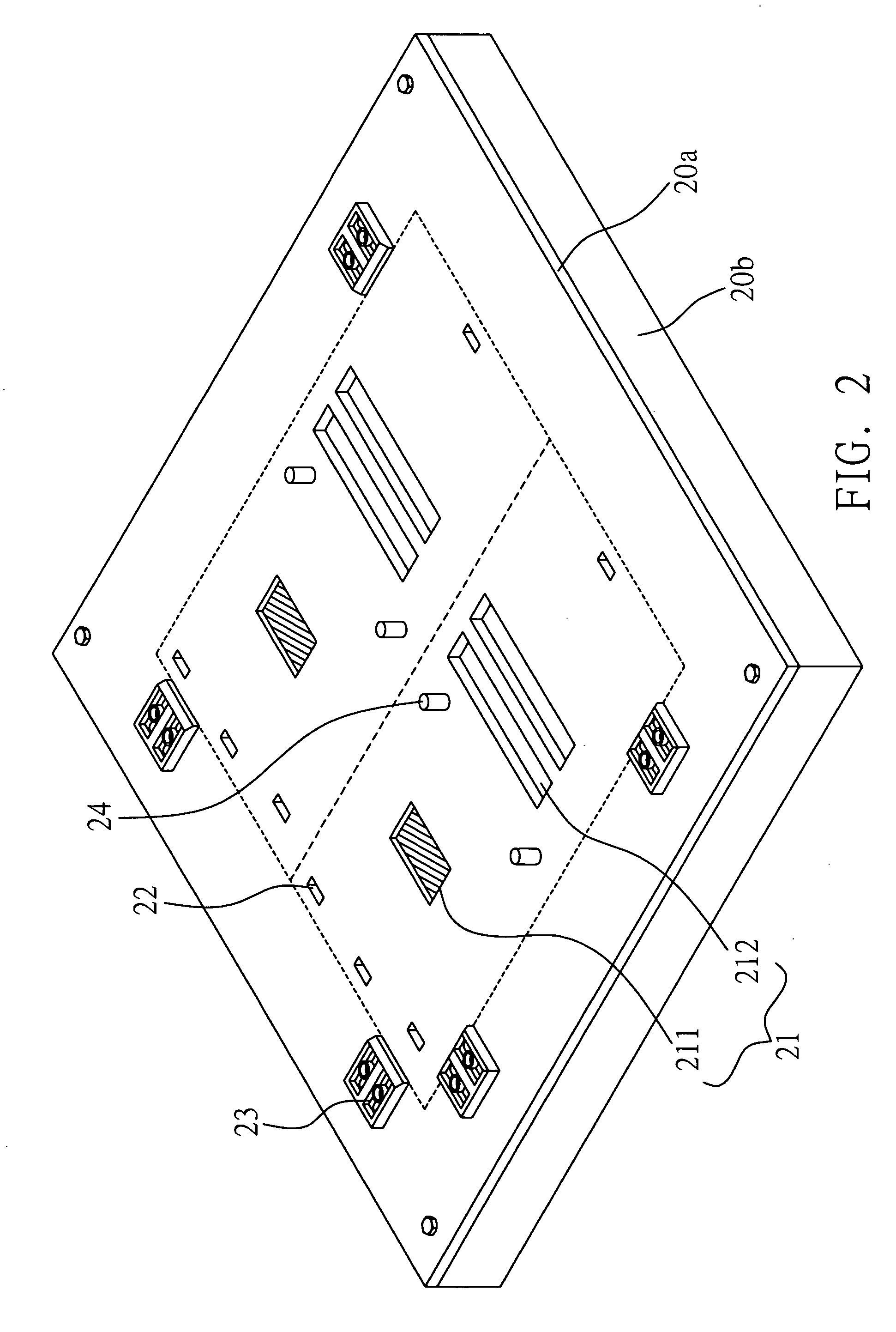
[0022] Referring to FIG. 2, a cutting fixture used to hold a printed circuit board mounted with electronic components during a cutting process is shown.

[0023] As seen in FIG. 2, the cutting fixture comprises a base 20b and a replaceable cover plate 20a mounted on the base 20b. The base 20b and the cover plate 20a jointly define a receiving space therebetween. The cover plate 20a comprises a plurality of openings 21 for receiving the electronic components of the printed circuit board, a plurality of cutting through holes 22 for allowing a cutting tool to pass through, a plurality of guide blocks 23 for engaging lateral sides of the printed circuit board, and positioning posts 24 for fixing the printed circuit board to the cover plate 20a.

[0024] The cover plate 20a is detachably secured to the base 20b by screws or latching components such that the cov...


PUM

PropertyMeasurementUnit
Sizeaaaaaaaaaa
Efficiencyaaaaaaaaaa

Abstract

A cutting fixture for a printed circuit board mounted with electronic components is proposed. The cutting fixture includes a base and a replaceable cover plate mounted on the base. The cover plate has openings for receiving the electronic components of the printed circuit board, cutting through holes for allowing a cutting tool to pass through, guide blocks for engaging lateral sides of the printed circuit board, and positioning posts for fixing the printed circuit board to the cover plate. Thus, a printed circuit board mounted with electronic components can be quickly and accurately fixed to the cutting fixture, thereby improving the cutting efficiency and cutting quality.

Description

BACKGROUND OF THE INVENTION [0001] 1. Field of the Invention [0002] The present invention relates to a cutting fixture for printed circuit boards, and more particularly to a cutting fixture for printed circuit boards mounted with electronic components. [0003] 2. Description of Related Art [0004] With rapid development of the science and technology, along with rapidly increasing demands for electronic products with multiple functions, modular designs and modular fabrication processes for printed circuit boards have become a mainstream on account of factors such as the economic efficiency and the production cost. [0005] In a conventional modular fabrication process for printed circuit boards, a plurality of printed circuit board units is first defined on a whole piece of printed circuit board module. Then, a plurality of circuit structures is formed on the whole piece of printed circuit board module corresponding to the printed circuit board units such that electronic components such ...

Claims


Application Information

Patent Timeline
IPC IPC(8): B26D7/02
CPCH05K3/0052H05K2203/0165H05K2203/0173H05K2203/0228H05K2203/167Y10T83/748
Inventor FENG, YAN-JUNNIU, QINGBAOSHIUE, CHIY-RAY
Owner INVENTEC CORP
Why Eureka
Eureka Blog
Learn More