
Occupant restraint system

a technology for occupants and restraints, applied in pedestrian/occupant safety arrangements, instruments, tractors, etc., can solve problems such as auto accidents, and achieve the effect of reducing the unnecessary activation of occupant restraint systems

Inactive Publication Date: 2007-05-24
DENSO CORP
View PDF2 Cites 3 Cited by
  • Summary
  • Abstract
  • Description
  • Claims
  • Application Information

AI Technical Summary

Benefits of technology

[0008] In view of the foregoing and other problems, it is an object of the present invention to provide an occupant restraint system, an unnecessary activation of which can be reduced.
[0011] Accordingly, an unnecessary activation of an occupant restraint system can be reduced.

Problems solved by technology

When an automobile receives a lateral impact, the automobile may roll over.

Method used


Image

  • Occupant restraint system
  • Occupant restraint system
  • Occupant restraint system

Examples


first embodiment

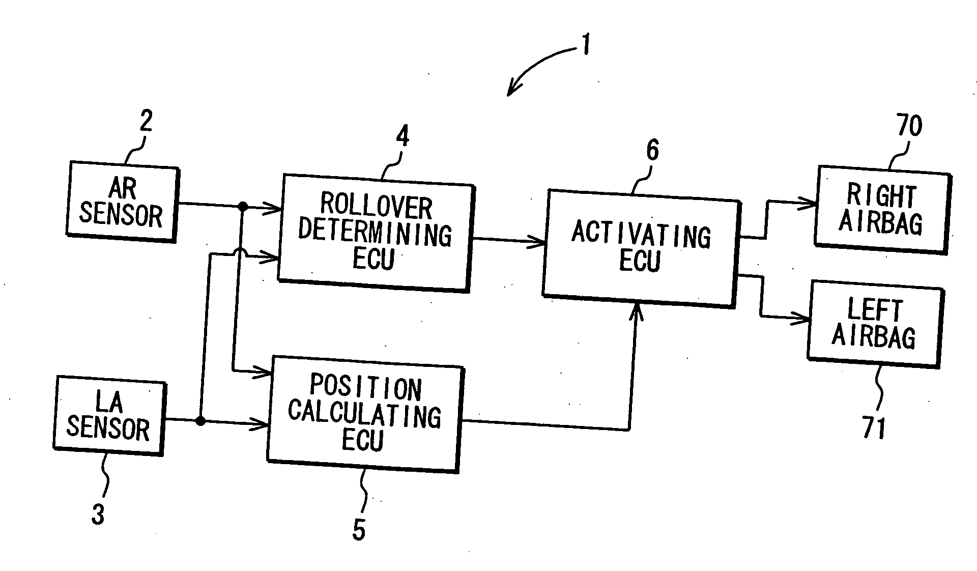
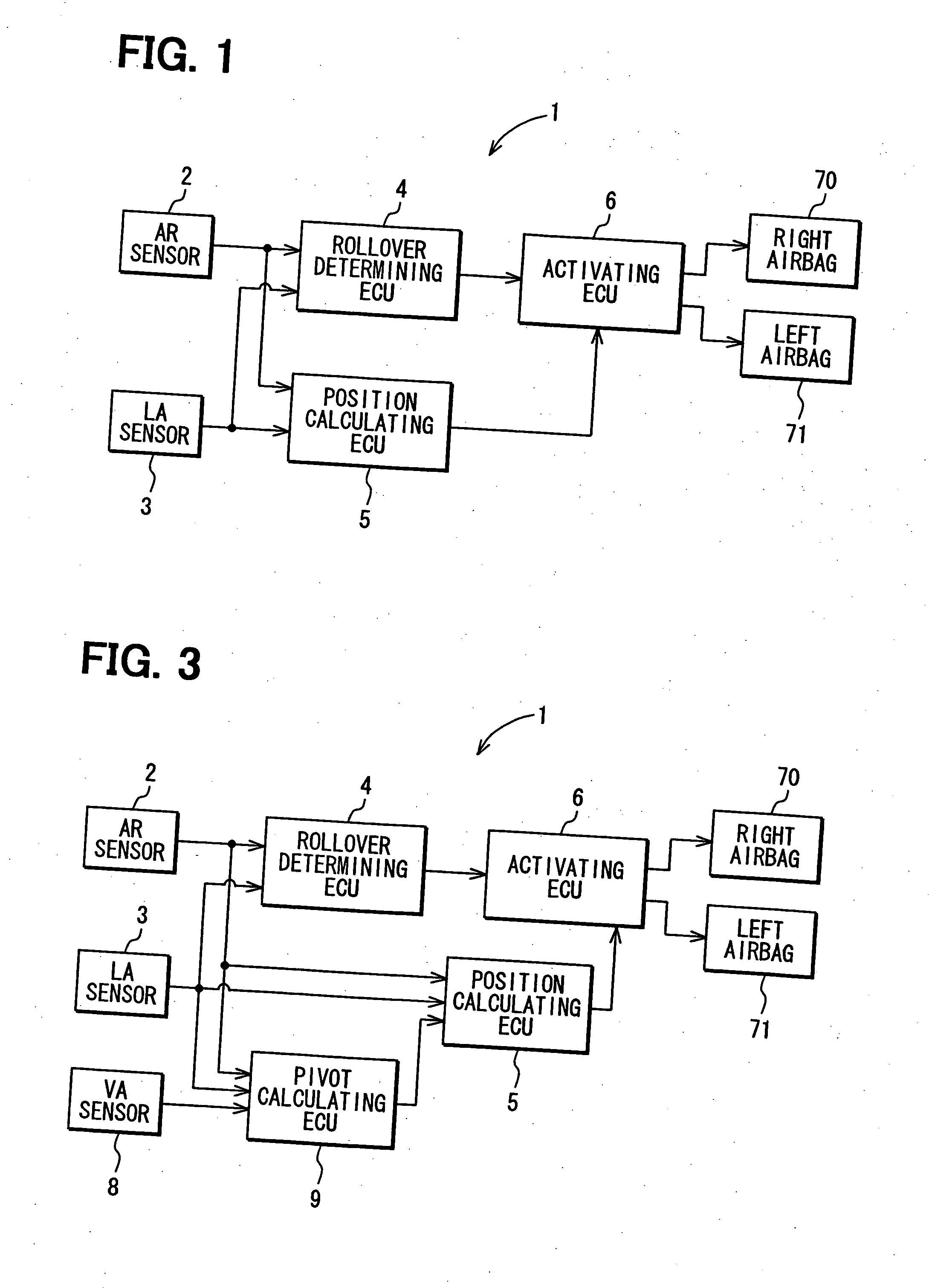
[0018] As shown in FIG. 1, an occupant restraint system 1 in a first embodiment includes an angular rate (AR) sensor 2, a lateral acceleration (LA) sensor 3, a rollover determining electronic control unit (ECU) 4, an occupant position calculating ECU 5, an airbag activating ECU 6, a right curtain airbag 70 and a left curtain airbag 71. The AR sensor 2 operates as a roll sensor. The ECUS 4, 5 and 6 operate as a determining device. The curtain airbags 70 and 71 operate as an occupant restraint device.

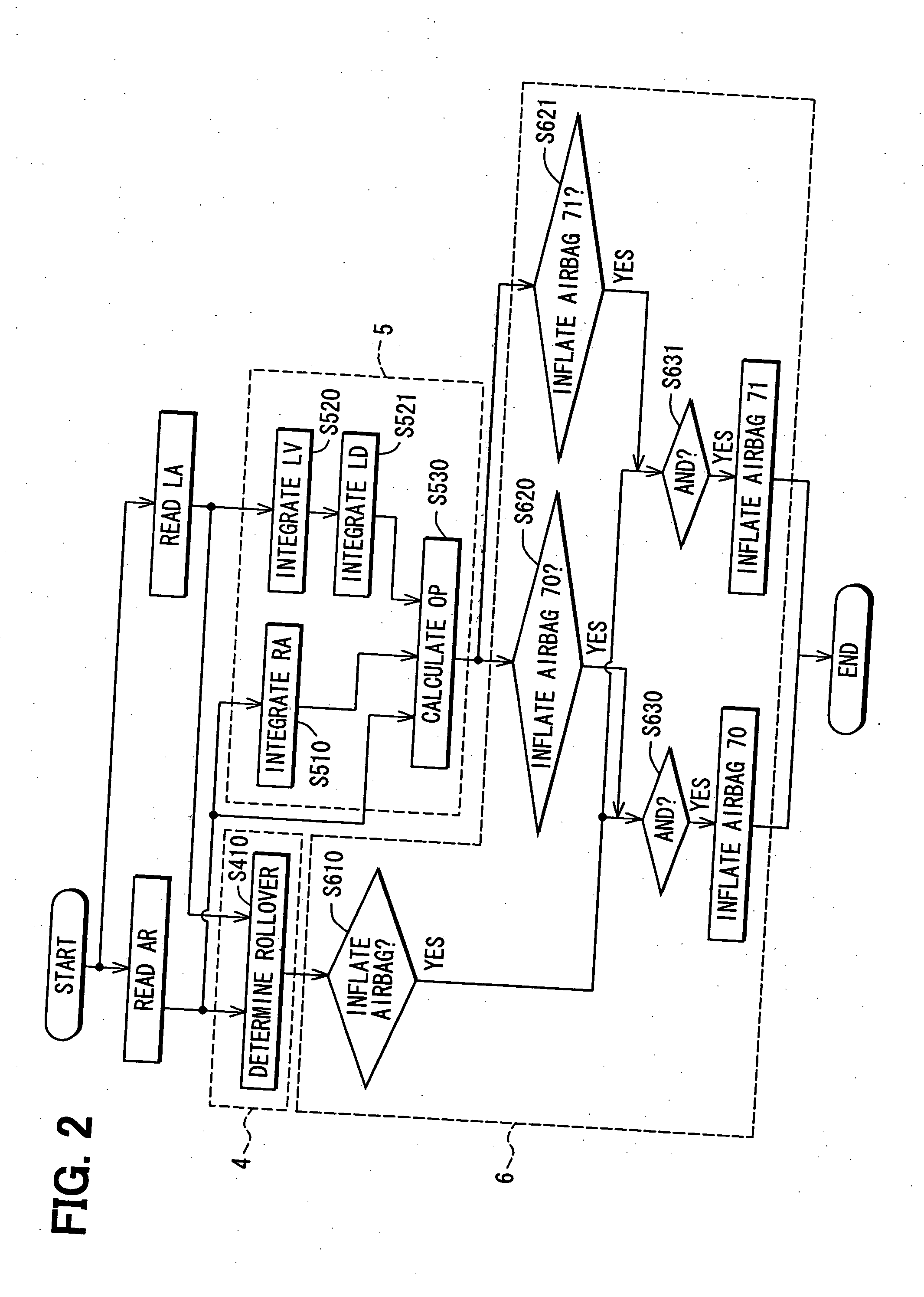
[0019] In the system 1, each of the sensors 2 and 3 is connected to each of the determining ECU 4 and the calculating ECU 5. A signal detected by each of the sensors 2 and 3 is input into each of the ECUS 4 and 5, and calculations are performed in the ECUS 4 and 5. The calculated results are transmitted to the activating ECU 6, and the ECU 6 controls each of the airbags 70 and 71.

[0020] Specifically, when an automobile equipped with the system 1 rolls over, signals detected by the senso...

second embodiment

[0026] As shown in FIG. 3, a system 1 in a second embodiment further includes a vertical, i.e., up-and-down direction, acceleration (VA) sensor 8 and a pivot point calculating ECU 9. The VA sensor 8 detects a vertical acceleration of an automobile. The ECU 9 calculates a pivot point for a rollover of an automobile by using signals detected by the sensors 2, 3 and 8. The calculation is performed as follows.

[0027] As shown in FIG. 4, an angular rate ω is generated by a rollover of an automobile, and a linear motion velocity Vr is generated at a measuring point X by the angular rate ω. The linear motion velocity Vr can be expressed as Formula 1.

Vr=R*ω  Formula 1:

[0028] In Formula 1, R represents a distance between the measuring point X and a pivot point (A or B) of the rollover. When the velocity Vr is resolved into a vertical, i.e., up-and-down, direction and a horizontal, i.e., automobile width, direction, a vertical velocity Vrz and a horizontal velocity Vry can be expressed as For...


PUM


Abstract

An occupant restraint system includes an occupant restraint device on a side face of an automobile interior, at least one of an acceleration sensor for detecting a lateral acceleration of the automobile and a roll sensor for detecting a roll of the automobile, and a determining unit. A detected signal is input into the determining unit. The determining unit determines a rollover or an overthrow of the automobile based on the detected signals, and calculates a head position of the occupant using the detected signals. Then, the determining unit activates the occupant restraint device, when the rollover is determined to have happened and the calculated head position is determined to be close to the occupant restraint device.

Description

CROSS REFERENCE TO RELATED APPLICATION [0001] This application is based on Japanese Patent Application No. 2005-334505 filed on Nov. 18, 2005, the disclosure of which is incorporated herein by reference in its entirety. BACKGROUND OF THE INVENTION [0002] 1. Field of the Invention [0003] The present invention relates to an occupant restraint system, which protects an occupant in an automobile when the automobile is in a lateral collision. [0004] 2. Description of Related Art [0005] An automobile is equipped with an occupant restraint system, which protects an occupant in the automobile when the automobile is in a collision. For example, an airbag is provided in an automobile as the occupant restraint system. The airbag is inflated so as to protect an occupant in the automobile. Further, the occupant restraint system is required not only for a collision in a back-and-forth direction but also for a lateral, i.e., side-to-side, impact. U.S. Pat. No. 7,076,353 (corresponding to JP-A-2004...

Claims


Application Information

Patent Timeline
Patent Type & Authority Applications(United States)
IPC IPC(8): B60R21/0132B60R21/16B60R21/015B60R21/20B60R21/232
CPCB60R21/0132B60R2021/0018B60R21/01552B60R21/01542B60R2021/01315B60R21/0133
Inventor OGATA, YOSHIHISA
Owner DENSO CORP
Learn More