Picture taking apparatus having focusing device

a technology of focusing device and picture taking apparatus, which is applied in the direction of camera focusing arrangement, printers, instruments, etc., can solve the problems of reducing the contrast of images, affecting the effect of focusing, and requiring time to move the photographing lens, so as to achieve the effect of maximizing the contrast of images

Inactive Publication Date: 2007-05-24
OM DIGITAL SOLUTIONS CORP
View PDF6 Cites 8 Cited by
  • Summary
  • Abstract
  • Description
  • Claims
  • Application Information

AI Technical Summary

Benefits of technology

[0008] According to one aspect of this invention, a picture taking apparatus capable of focusing on one of a plurality of distance measuring points in a picture for photography, comprising: a focus detecting device capable of obtaining distance information of each of the plurality of distance measuring points; a control section for controlling a photographing operation of the apparatus to select one distance measuring point from the plurality of distance measuring points by using the distance information obtained by the focus detecting device and to display the selected distance measuring point on a display member; and a focusing device capable of focusing a subject lying at the selected distance measuring point to maximize the contrast of an image of the subject.
[0009] According to another aspect of this invention, a focusing method for use with a picture taking apparatus capable of focusing on one of a plurality of distance measuring points in a picture for photography, comprising: selecting one distance measuring point from the plurality of distance measuring points by using an image signal of a subject or distance information on the subject; displaying an indicator of the selected distance measuring point in such a manner as to superimpose the indicator on a subject image; accepting an input change signal for changing the distance measuring point; changing the displayed distance measuring point to another distance measuring point in response to the change signal; and focusing a subject lying at the other distance measuring point to maximize the contrast of an image of the subject, wherein the steps of accepting an input change signal and changing the displayed distance measuring point are performed before any focusing on the initially selected distance measuring point.

Problems solved by technology

Accordingly, with digital cameras, time to move the photographing lens is needed and this so-called release time lag may become long.
Consequently, repeating focusing takes time and delays photography.
This delay may become unacceptable particularly if the hill-climbing auto-focusing method is used.

Method used


Image

  • Picture taking apparatus having focusing device
  • Picture taking apparatus having focusing device
  • Picture taking apparatus having focusing device

Examples


Embodiment Construction

[0031] A first example will be described below with reference to FIGS. 1 to 5.

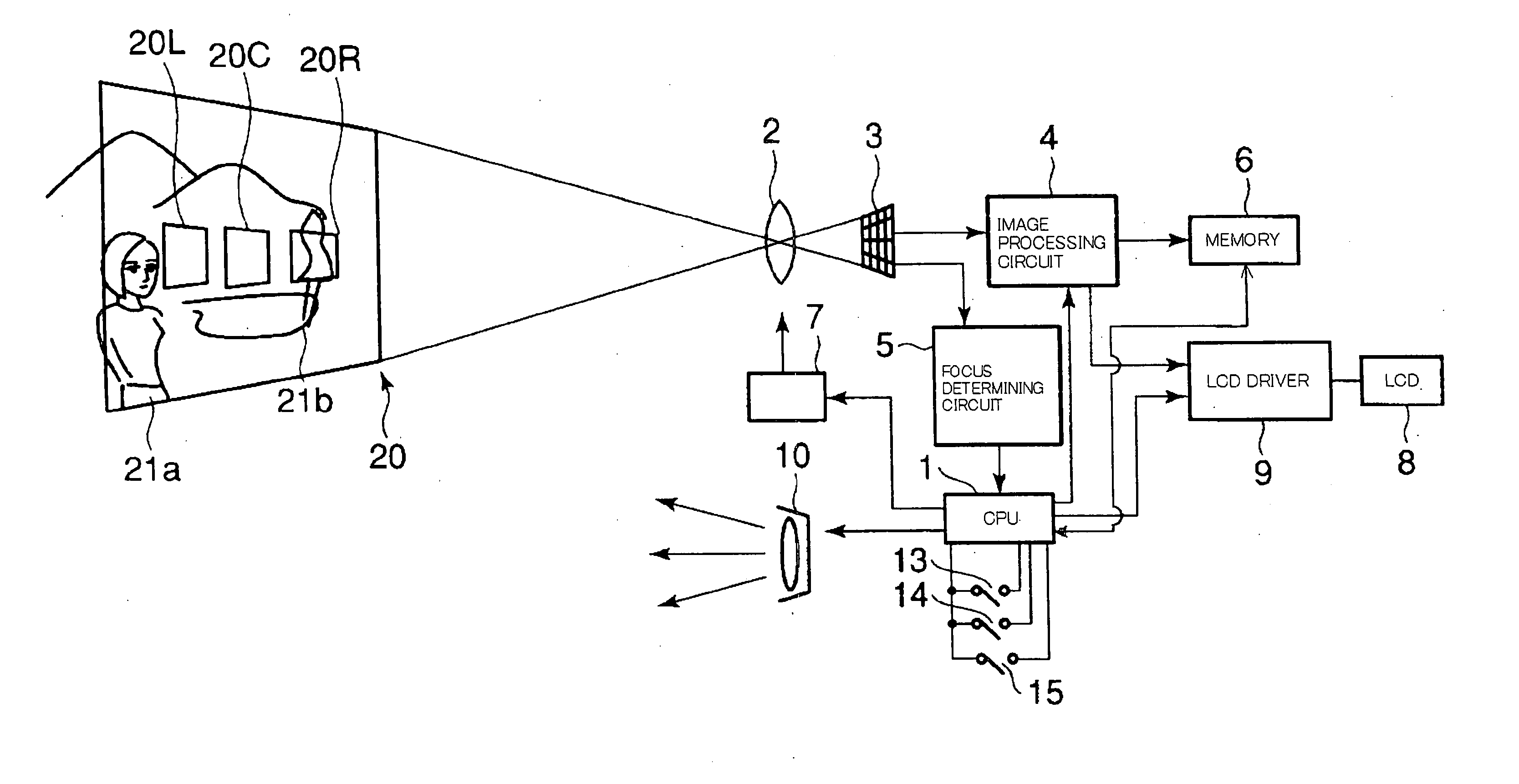
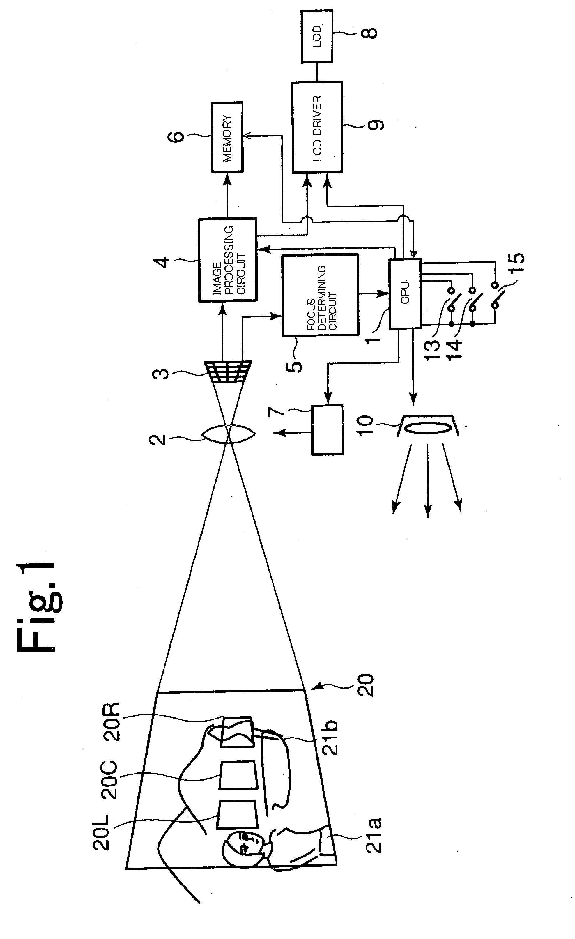
[0032]FIG. 1 is a block diagram showing components of a camera according to a first example.

[0033] Referring to FIG. 1, a CPU 1 is an arithmetic and control section composed of a one-chip microcomputer and the like. Connected to this CPU 1 are a photographing lens driver (LD) 7 for driving a photographing lens 2, an image processing unit (e.g., circuit) 4 and a focus determining unit (e.g., circuit) 5, an image pickup element 3 which receives a photographing light beam entering through the photographing lens 2, a memory 6 which is a storage section, an LCD driver 9 for driving an LCD 8 which is an image display section, and an electronic flash 10. The image processing circuit 4 and the focus determining circuit 5 are each supplied with the output from the image pickup element 3. Incidentally, the image pickup element 3 may use, for example, an area sensor.

[0034] A release switch (button) 13, a mode chan...


PUM


Abstract

A plurality of distance measuring points in a picture can be correctly and rapidly focused on. Images at a plurality of distance measuring points in the picture can be detected through a photographing lens by means of an image pickup element. These detected distance measuring points can be displayed on a monitor screen. Finally, a photographing lens can be controlled with respect to the displayed distance measuring points so as to cause the output from the image pickup element to reach its highest contrast.

Description

CROSS-REFERENCE TO RELATED APPLICATION [0001] This application is a divisional of U.S. patent application Ser. No. 10 / 364,444, filed on Feb. 11, 2003. which claims the benefit of Japanese Patent Application No. 2002-41,823, filed on Feb. 19, 2002, in Japan. The contents of each of these applications are incorporated by reference.BACKGROUND OF THE INVENTION [0002] 1. Field of the Invention [0003] This invention relates to a picture taking apparatus, such as cameras, having a focusing device, and more particularly, to digital cameras. [0004] 2. Description of the Related Art [0005] A digital camera has image pickup means for electrically detecting an image of a subject through a photographing lens. It is widely known that digital cameras perform focusing using an image signal outputted from the image pickup means. This auto focus technology finely adjusts the focus of the photographing lens to find a lens position where the contrast of an image becomes highest. Accordingly, with digit...

Claims


Application Information

Patent Timeline
Patent Type & Authority Applications(United States)
IPC IPC(8): G03B13/00H04N5/232G02B7/28G02B7/36G03B13/36G03B17/18H04N5/225H04N101/00
CPCH04N5/23212H04N23/673H04N23/634
Inventor NONAKA, OSAMU
Owner OM DIGITAL SOLUTIONS CORP
Why Eureka
Try Eureka