
Lightening apparatus

Active Publication Date: 2007-05-24
SUZHOU LEKIN SEMICON CO LTD
View PDF9 Cites 32 Cited by
  • Summary
  • Abstract
  • Description
  • Claims
  • Application Information

AI Technical Summary

Benefits of technology

[0007] The present invention provides a li

Problems solved by technology

Advantages of the LED are that no inverter is required, power consumption is low, and a service life thereof is longer as compared with the CCFL.
However, since the brightness of the LED is lower than that of the CCFL, it is difficult to use the LED as a lightening.

Method used


Image

  • Lightening apparatus
  • Lightening apparatus
  • Lightening apparatus

Examples


Embodiment Construction

[0018] Reference will now be made in detail to the preferred embodiments of the present invention, examples of which are illustrated in the accompanying drawings. Wherever possible, the same reference numbers will be used throughout the drawings to refer to the same or like parts.

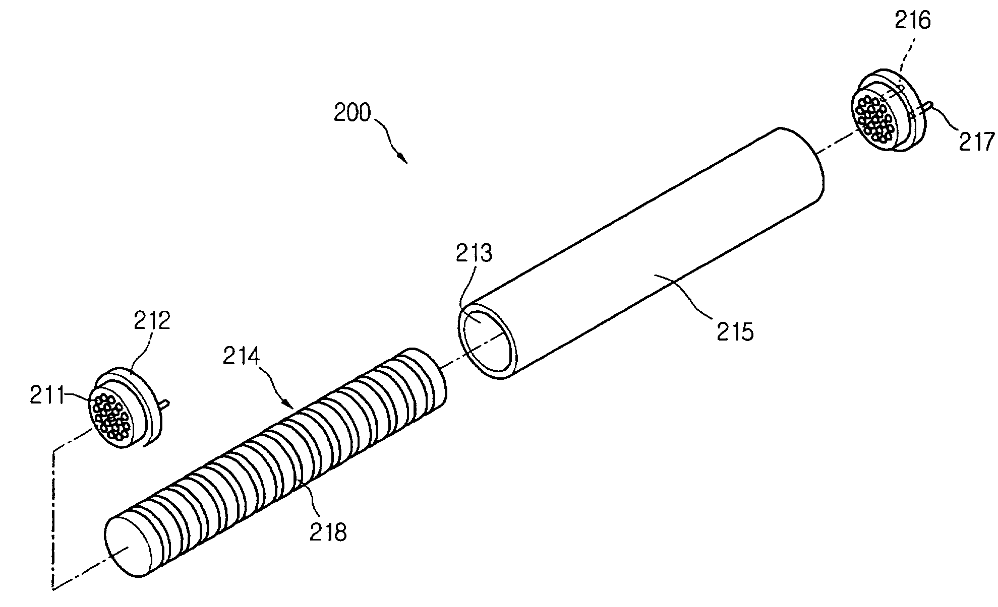
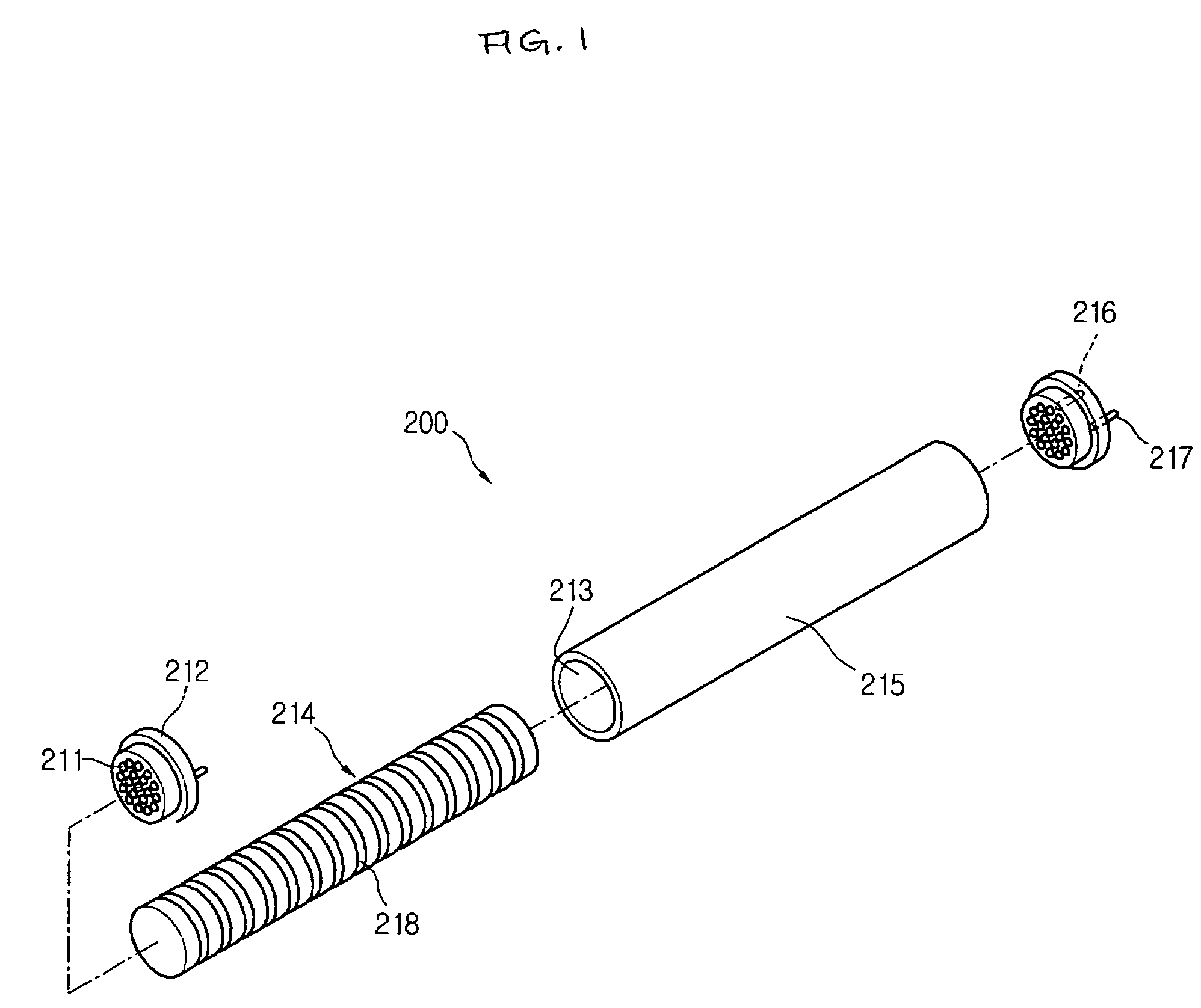
[0019]FIG. 1 is a view of a lightening apparatus according to an embodiment of the present invention.

[0020] Referring to FIG. 1, a lightening apparatus 200 of an embodiment of the present invention includes an LED module 212 having a plurality of LEDs 211 and connection terminals 216 and 217 for supplying electric power to the LEDs 211, a diffusing guide 214 for diffusing light emitted from the LEDs 211, and a cover 215 in which the diffusing guide 214 is inserted and installed.

[0021] The lightening apparatus 200 including the connection terminals 216 and 217 are designed to have a size and shape that can be compatible with the conventional fluorescent lamp.

[0022] The diffusing guide 214 may be formed i...


PUM


Abstract

A lightening apparatus includes an LED (Light Emitting Diode) module having a plurality of LEDs and a connection terminal for supplying electric power, a diffusing guide for diffusing light emitted from the LEDs, and a cover in which the diffusing guide is installed and to which the LED module is coupled.

Description

BACKGROUND OF THE INVENTION [0001] 1. Field of the Invention [0002] The present invention relates to a lightening apparatus using a light emitting diode. [0003] 2. Description of the Related Art [0004] As a high luminance white light emitting diode (LED) has been developed, it has replaced a cold cathode fluorescent lamp (CCFL). [0005] Advantages of the LED are that no inverter is required, power consumption is low, and a service life thereof is longer as compared with the CCFL. However, since the brightness of the LED is lower than that of the CCFL, it is difficult to use the LED as a lightening. SUMMARY OF THE INVENTION [0006] Accordingly, the present invention is related to a lightening apparatus that substantially obviates one or more problems due to limitations and disadvantages of the related art. [0007] The present invention provides a lightening apparatus having a high luminance. [0008] The present invention provides a lightening apparatus that is compatible with a conventio...

Claims


Application Information

Patent Timeline
IPC IPC(8): H01L33/00F21V3/04H01L33/44H01L33/50
CPCF21K9/52F21Y2101/02G02B6/001F21Y2113/005G02B6/0063G02B6/0068F21K9/17G02B6/0038F21K9/27F21K9/61F21Y2113/13F21Y2115/10F21K9/64
Inventor PARK, JUN SEOK
Owner SUZHOU LEKIN SEMICON CO LTD
Learn More