
Techniques configuring customer equipment for network operations from provider edge

a customer equipment and network operation technology, applied in the field of customer premises network nodes, can solve the problems of double handling, variable complexity of customer networking requirements, and inability to complete the final configuration file,

Active Publication Date: 2007-05-24
CISCO TECH INC
View PDF14 Cites 92 Cited by
  • Summary
  • Abstract
  • Description
  • Claims
  • Application Information

AI Technical Summary

Problems solved by technology

A challenge for service providers in providing CE management services is the variability and complexity of customer networking requirements, and the flexibility offered by different hardware and software platforms to serve as the CE node.
In one approach, a skilled technician from the service provider accompanies the CE node device to the customer premises and installs and configures the device for the customer This approach is expensive in technician time and travel and introduces delays as devices otherwise ready are not shipped until there are technicians available to accompany them.
There are some disadvantages with the staging center approach.
One disadvantage is that the staging center is often different from the manufacturing locations, so a device is manufactured, packed and shipped to the staging center.
This double handling adds to the delay and the cost of supplying the managed CE node.
Another disadvantage arises when the systems engineer has not completed the final configuration files.
In some such cases, the staging process is delayed until the systems engineer completes the determination of the configuration files.
Another disadvantage arises when a systems engineer has composed configuration data using a text-editor and has introduced typographical errors.
At the staging center, an error or exception will occur.
The device is then put aside until the problem can be diagnosed, thus further delaying the delivery of a configured device to the customer premises.
Another disadvantage arises when the device is configured based on erroneous information from the customer.
As another example, the SP requires the CE device to connect with Frame Relay protocol but the device is erroneously configured for HDLC Protocol.
Another disadvantage arises because a pre-configured device in the staging is not fungible with another device of the same model that is not configured or is configured for a different customer or customer premises.
There is an increased chance for an error in which the correctly pre-configured device is shipped to the wrong location or marked for the wrong LAN.
This approach suffers from the same delays of double handling experienced by the approach that employs full configuration at the staging center.
If multiple configuration servers are used, this approach also suffers the increased chance of shipping the device to the wrong destination for which its configuration server does not have configuration data.
Another disadvantage of this approach is that the configuration server cannot be changed without a manual change to the address of the configuration server, often executed by a visit of a highly skilled technician to the customer premises, and the associated costs.

Method used


Image

  • Techniques configuring customer equipment for network operations from provider edge
  • Techniques configuring customer equipment for network operations from provider edge
  • Techniques configuring customer equipment for network operations from provider edge

Examples


Embodiment Construction

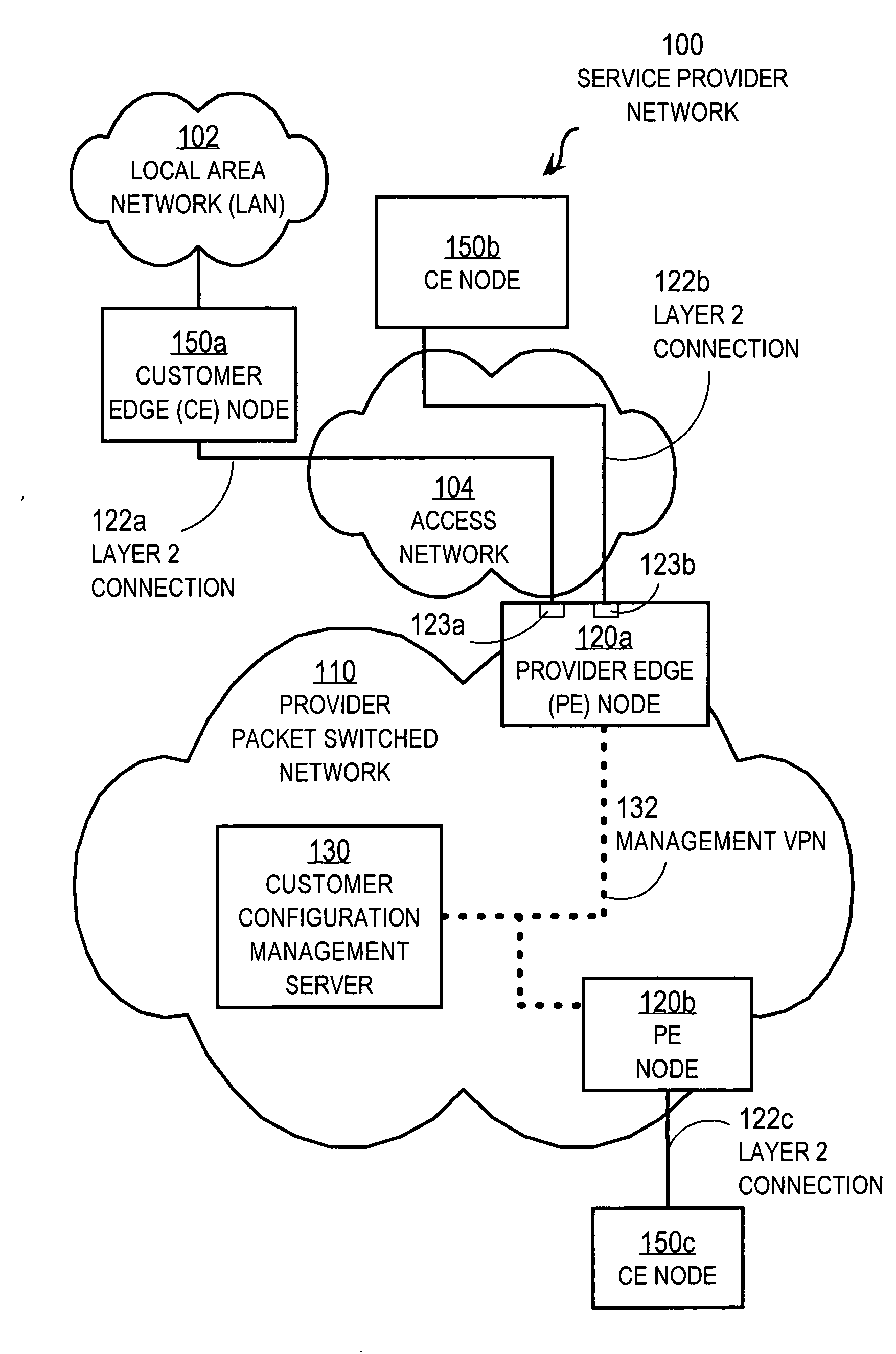
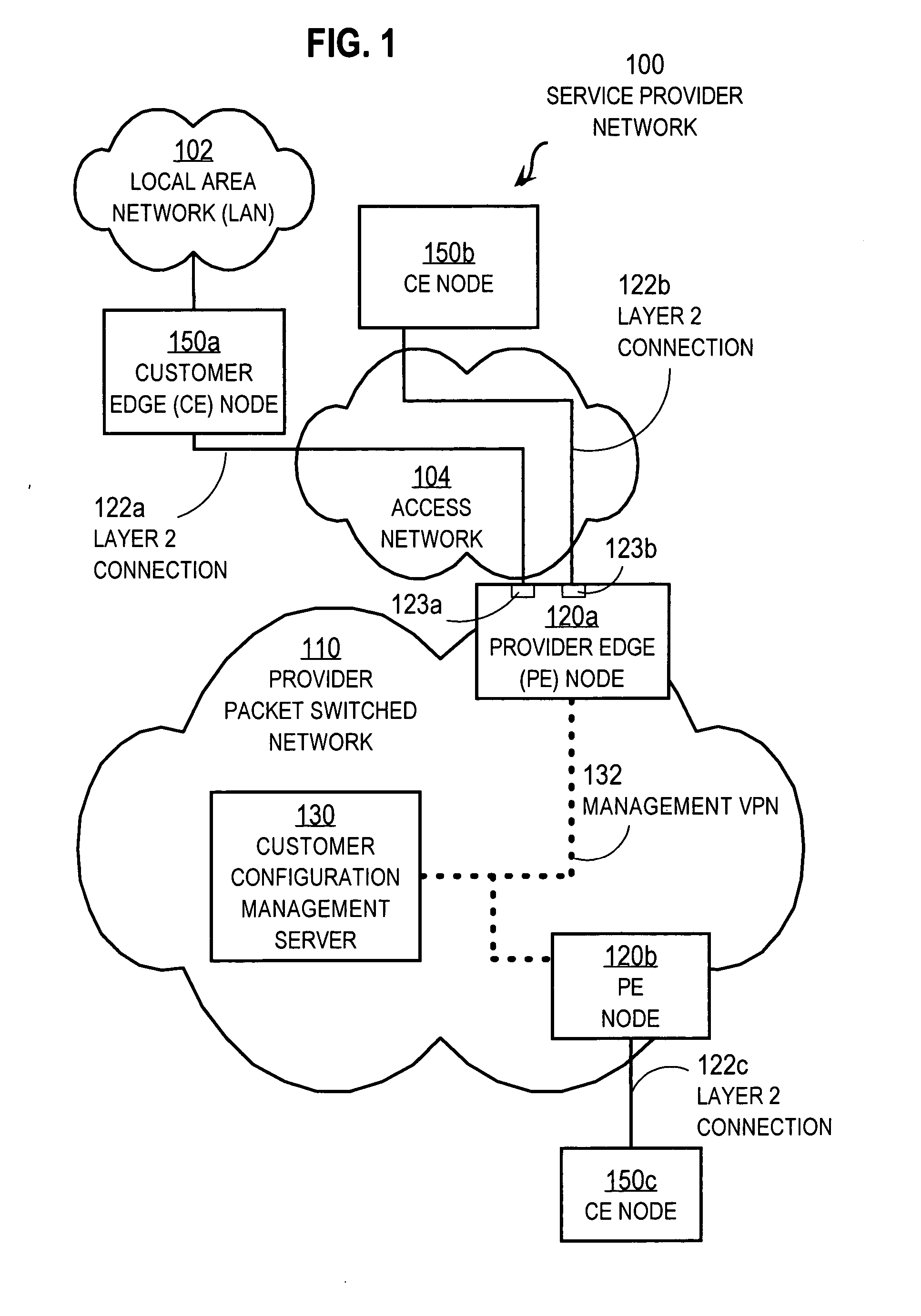
[0034] A method and apparatus are described for configuring customer edge (CE) nodes from a service provider network. In the following description, for the purposes of explanation, numerous specific details are set forth in order to provide a thorough understanding of the present invention. It will be apparent, however, to one skilled in the art that the present invention may be practiced without these specific details. In other instances, well-known structures and devices are shown in block diagram form in order to avoid unnecessarily obscuring the present invention.

[0035] Certain embodiments of the invention are described in the context of a customer equipment edge (CE) node connected directly to a provider edge (PE) node of a provider network for a provider who manages the CE node and obtaining configuration data from a single customer configuration management server (CMS). However, the invention is not limited to this context. In other embodiments more CMSs are used to configur...


PUM


Abstract

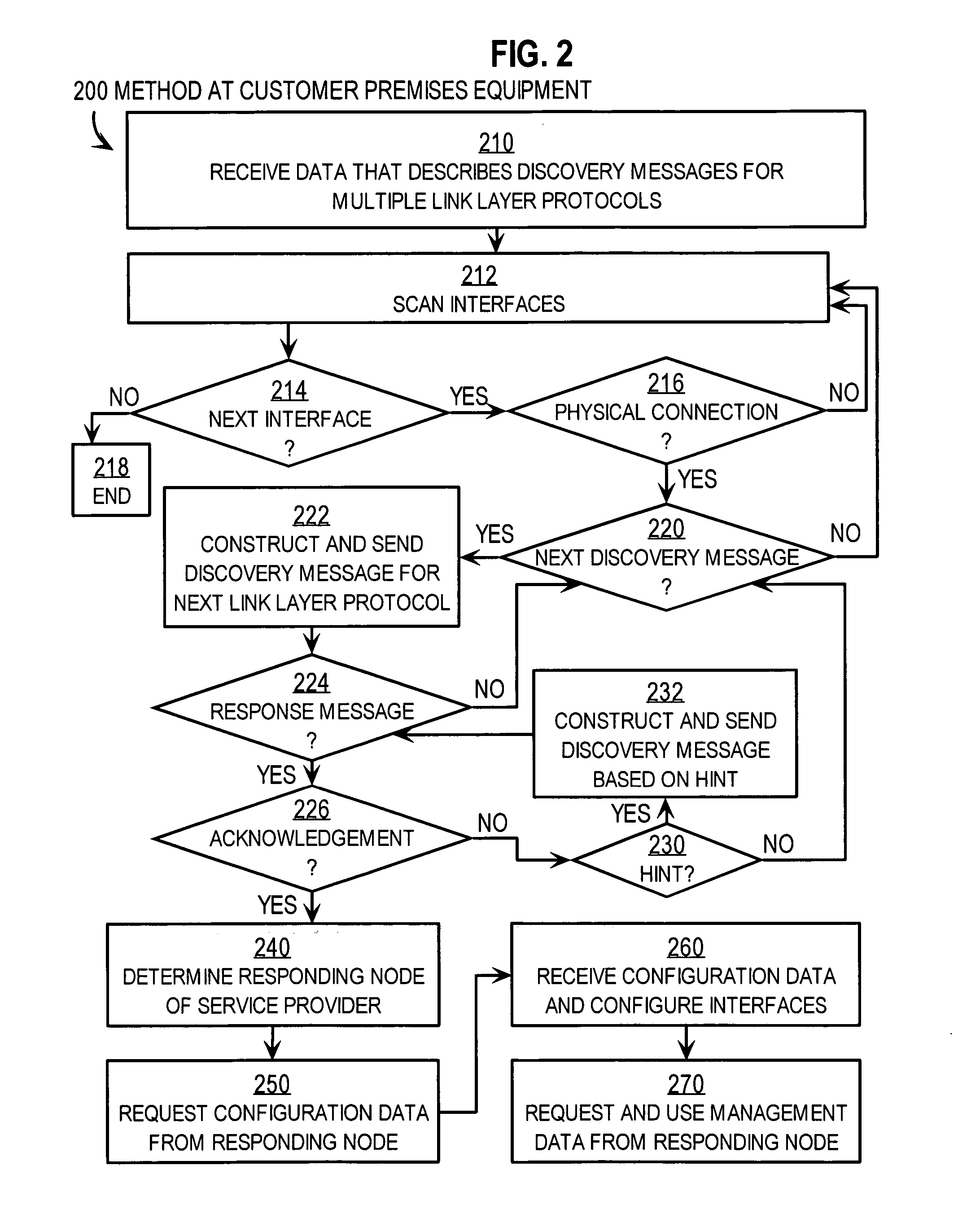
Techniques for configuring customer premises equipment for communication with a provider network include establishing a physical layer network connection between a particular customer node and a first provider node. The particular customer node is an intermediate network node on a customer premises. The first provider node is an intermediate network node on a first provider network of a first service provider different from the customer. Configuration data for one or more network interfaces on the particular customer node are automatically received through the physical layer network connection. The particular customer node is automatically configured based on that configuration data. The automatic provisioning of the customer node allows equipment to be more economically shipped and installed at customer premises and allows upgraded or replacement equipment to be more economically swapped in place of equipment previously installed. Traffic management data can also be automatically received and used at the particular customer node.

Description

BACKGROUND OF THE INVENTION [0001] 1. Field of the Invention [0002] The present invention relates to configuring a customer premises network node for network operations with a provider network; and, in particular, to using a network service provider edge node to configure a customer premises node in a communications network without pre-configuring the customer premises node with a network address of a configuration server on the provider network. [0003] 2. Description of the Related Art [0004] Networks of general purpose computer systems and other devices connected by external communication links are well known and widely used in commerce. The networks often include one or more network devices that facilitate the passage of information between the computer systems and other devices. A network node is a network device or computer system or other device connected by the communication links. [0005] Information is exchanged between network nodes according to one or more of many well kno...

Claims


Application Information

Patent Timeline
Patent Type & Authority Applications(United States)
IPC IPC(8): H04L12/56
CPCH04L41/0806H04L41/0869
Inventor MAMMOLITI, VINCENT JOHNMULLOOLY, JOHN
Owner CISCO TECH INC
Learn More