Radio-frequency (RF) power portal

Active Publication Date: 2007-05-24
POWERCAST
View PDF20 Cites 211 Cited by
  • Summary
  • Abstract
  • Description
  • Claims
  • Application Information

AI Technical Summary

Problems solved by technology

Even with power conscious designs and the latest in battery technology, many devices do not meet the lifetime cost and maintenance requirements for applications that require a large number of untethered devices such as logistics and building automation.
For both device types, scheduled power-source maintenance is costly and can be disruptive to the entire system that a device is intended to monitor and / or control.
Unscheduled maintenance trips are even more costly and disruptive.
On a macro level, the relatively high cost associated with the internal battery also reduces the practical, or economically viable, number of devices that can be deployed.
However, this ideal solution may not always be practical to implement due to low energy in the environment, and site restrictions may limit the ability to use a dedicated energy supply.
The technology disclosed in U.S. Pat. No. 6,127,799 is limited by the fact that the power conversion efficiency of the antenna array is dependent on the number of dipoles.
Additionally, U.S. Pat. No. 6,127,799 discloses the use of dipole antennas, which may not be practical for most battery-operated devices due to the size of the antenna and antenna array.
This prior disclosure, states that the dipole antennas are used to cover more than one side of a battery that has a width of 12.5 cm which makes in impractical for certain devices and battery sizes.
There are also limitations on the battery that can be used with the prior disclosure due to metal pieces inside the battery, which tend to absorb RF energy.
The devices in these patents are limited by the fact that they can only receive power in the inductive or near-field region.

Method used


Image

  • Radio-frequency (RF) power portal
  • Radio-frequency (RF) power portal
  • Radio-frequency (RF) power portal

Examples


Embodiment Construction

[0023] A complete understanding of the invention will be obtained from the following description when taken in connection with the accompanying drawing figures wherein like reference characters identify like parts throughout.

[0024] For purposes of the description hereinafter, the terms “upper”, “lower”, “right”, “left”, “vertical”, “horizontal”, “top”, “bottom”, and derivatives thereof shall relate to the invention as it is oriented in the drawing figures. However, it is to be understood that the invention may assume various alternative variations and step sequences, except where expressly specified to the contrary. It is also to be understood that the specific devices and processes illustrated in the attached drawings, and described in the following specification, are simply exemplary embodiments of the invention. Hence, specific dimensions and other physical characteristics related to the embodiments disclosed herein are not to be considered as limiting.

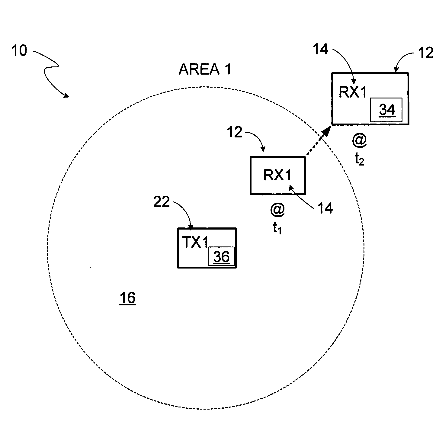
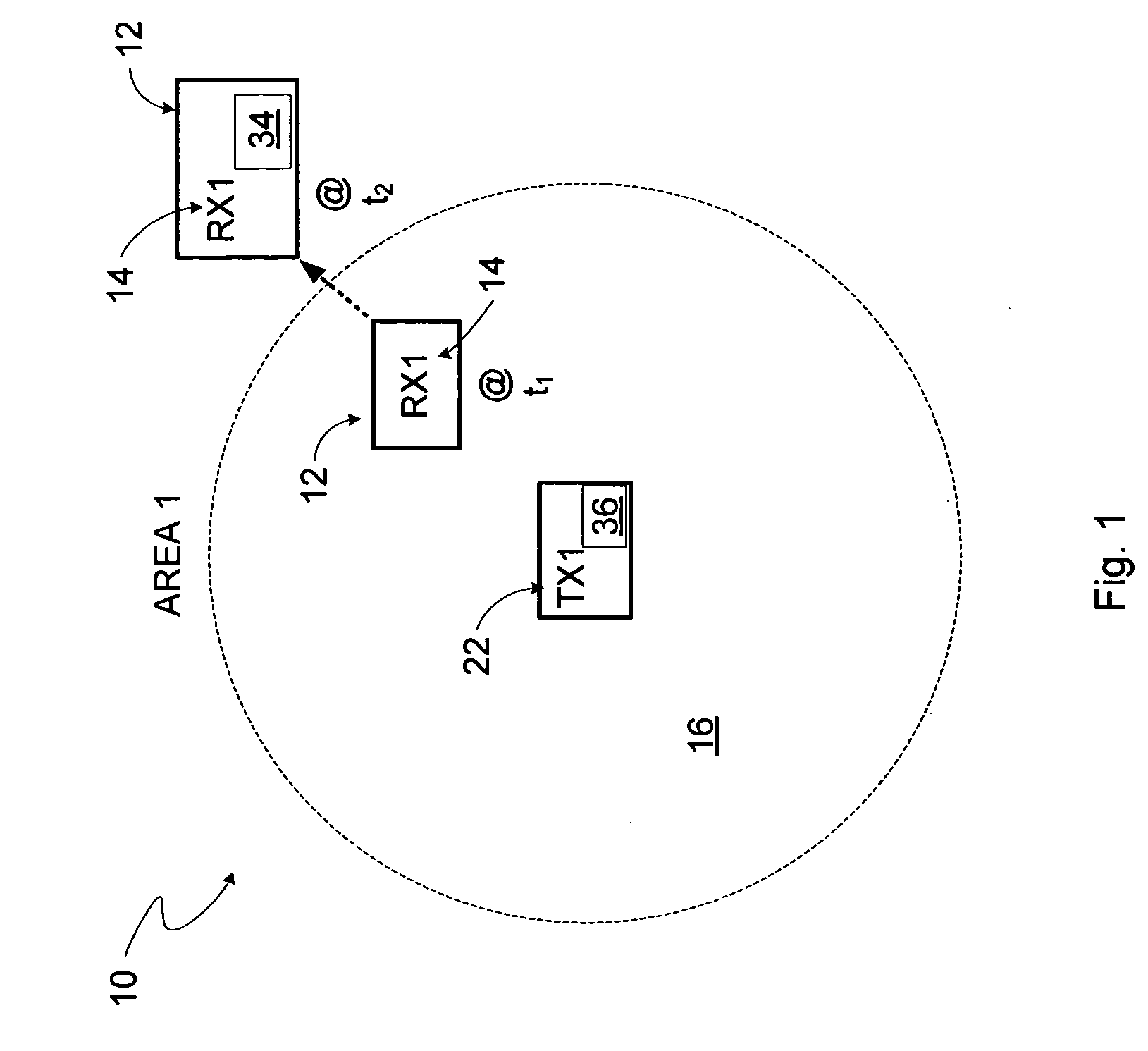
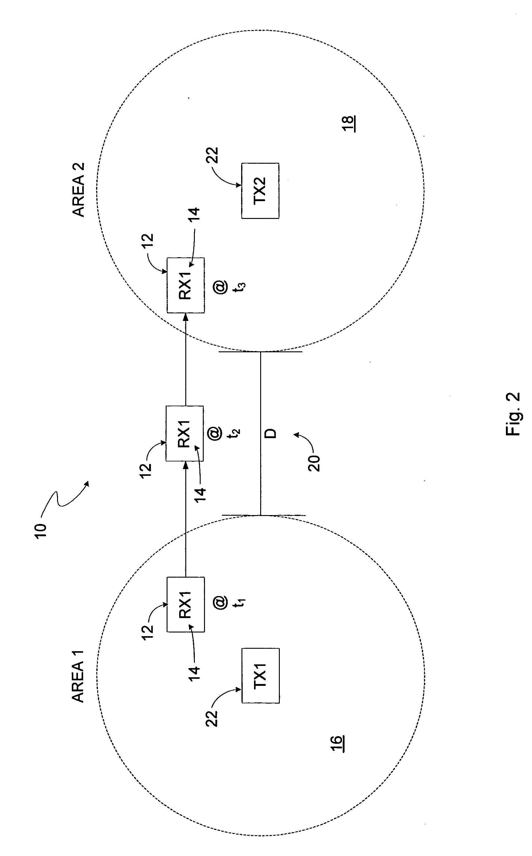
[0025] Referring now to t...


PUM


Abstract

A system for powering a mobile device having an energy harvester which receives wireless energy and converts the energy into current includes a first portal in which wireless energy is transmitted for the energy harvester of the mobile device to receive and convert it into current when the device is in the first portal. The system comprises a second portal separate and apart from the first portal with a gap between the first portal and the second portal, the second portal in which wireless energy is transmitted for the energy harvester of the mobile device to receive and convert it into current after the device has passed through the first portal and the gap and is in the second portal. A method for powering a mobile device having an energy harvester which receives wireless energy and converts the energy into current is also disclosed.

Description

CROSS-REFERENCE TO RELATED APPLICATIONS [0001] This application claims the benefit of U.S. Provisional Patent Application Ser. No. 60 / 738,523, filed Nov. 21, 2005.BACKGROUND OF THE INVENTION [0002] 1. Field of the Invention [0003] The present invention relates to a system for powering a mobile device having an energy harvester which receives wireless energy and converts the energy into current. More specifically, the present invention relates to a system for powering a mobile device having an energy harvester which receives wireless energy and converts the energy into current when it is in a portal in which wireless energy is transmitted for the energy harvester of the mobile device. [0004] 2. Description of Related Art [0005] As processor capabilities have expanded and power requirements have decreased, there has been an ongoing explosion of devices that operate completely independent of wires or power cords. These “untethered” devices range from cell phones and wireless keyboards ...

Claims


Application Information

Patent Timeline
IPC IPC(8): H03D7/16H04B1/10H04B1/16H04B1/38
CPCG06K19/0707H02J17/00H04B1/1607H02J50/20H02J50/001H02J50/70H02J50/402H02M3/24
Inventor GREENE, CHARLES E.HARRIST, DANIEL W.SHEARER, JOHN G.
Owner POWERCAST
Why Eureka
Try Eureka